09/01 IPN: M5000-00-102
Reassembling the radio D - 15
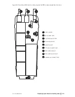
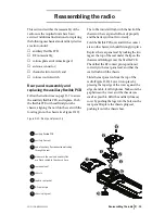
Figure D-12: Assembly of the switches
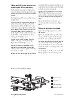
Fitting the front panel to the
chassis
Place the radio into the front panel top first,
inserting the antenna connector and knob
switches through the holes. Gently ease the
radio into the front panel until the edge of the
chassis is flush with the edge of the front panel,
while making sure that the seal is not pinched;
using the battery as leverage as in radio disas-
sembly may be helpful. Replace the two chassis
screws at the base of the radio, tightening them
to 2 inch pounds.
Replace the two knobs on the radio with new
knobs, after placing a spot of Loctite™ 680 on
each switch shaft. Make sure there is no gap
between the base of each knob and the knob
label by firmly pressing the top of each knob
against a firm surface. Choose a surface that will
not damage the top of the knob.
8
9
7
4
5
6
2
1
3
6
6
8
shield
chassis
antenna connector
channel selector switch
on/off/volume control switch
ribbed lock washer (M6*10*0.7 mm)
SMA connector nut (¼*7.9*3 mm)
channel/volume control nut
(M6*7.9*3 mm)
knob seal
1
2
3
4
5
6
7
8
9


