8.16.2
T2000-A03/-A04/-A16 Remote Loom Kits
M2000-00
31/12/97
Copyright TEL
8.16.1 Components Required
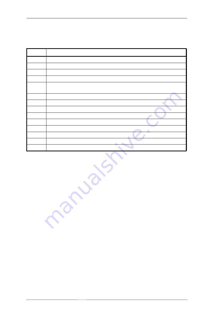
The T2000 remote loom kits contain the following components:
8.16.2 Fitting To Locally Mounted Radios
1
Remove the top cover of the radio by unscrewing the 4 bottom cover screws.
Remove the 3 logic PCB retaining screws and fold back the logic PCB. If necessary,
remove the 3 option PCB mounting screws before lifting the logic PCB.
Remove the microprocessor shield retaining screws and the screw securing the
control head ground lead, then remove the microprocessor shield.
Remove the bottom cover of the radio and unplug the loom running between the
control head and the logic PCB (on EMC model radios, the loom runs between the
control head and the EMC filter PCB).
The control head can now be detached from the chassis.
Remove the 4 adaptor plate retaining screws from the control head and remove
the adaptor plate from the back of the con
trol head.
2
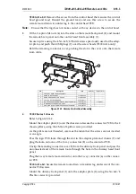
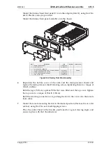
Refer to Figure 8.16.1.
Unclip the remote back panel remoting connector cover (3).
Pass one end of the remote loom through the connector cover hole and plug onto
the 8 way connector (6) on the top side of the control head PCB.
T2000-A03 & T2000-A04 kits:
Remove the ground lead from under one of the con-
trol head PCB screws, and discard the ground lead.
Quantity
Description
1
remote loom, complete with 8 way connectors
1
remote mounting bracket
1
remote back panel
1
dummy front panel
2
remoting connector cover (fitted to the remote back panel & dummy front
panel)
2
M4 pressed captive nut (for remote control head assembly)
2
thumbscrew (for remote mounting bracket)
4
ESD plug (to fit over remote back panel screw heads: T2000-A16 only)
2
No 6x3/4 self-tapping screw (for remote mounting bracket)
4
No 4x 3/8 pan Pozi Plastite screw (dummy front panel mounting)
2
M3x6 pan Pozi Taptite screw (connector PCB mounting)
4
M3x8 pan Pozi Taptite screw (EMC filter PCB mounting)
1
EMC filter PCB (Series II radio chassis)
1
connector PCB (Series I radio chassis)
Summary of Contents for T2000 SERIES II
Page 64: ...7 9 2 T2000 TCXO Tx Audio PCB M2000 00 31 10 96 Copyright TEL IPN 220 01389 00 ...
Page 66: ...7 9 8 T2000 TCXO Tx Audio PCB M2000 00 31 12 97 Copyright TEL IPN 220 01389 02 ...
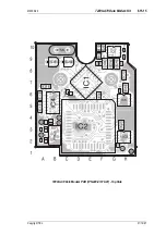
Page 94: ...7 14 4 T2020 T2040 T2050 Control Head PCB M2000 00 31 10 96 Copyright TEL IPN 220 01321 04 ...
Page 98: ...7 16 2 T2000 EMC Filter PCB M2000 00 31 10 96 Copyright TEL IPN 220 01383 01 ...
Page 100: ...7 17 2 T2000 Data Interface Decoupling PCB M2000 00 31 10 96 Copyright TEL IPN 220 01388 01 ...
Page 102: ...8 2 Accessories M2000 00 31 12 97 Copyright TEL ...
Page 110: ...8 10 6 T2000 A450X CTCSS Scrambler Kit M2000 00 31 12 97 Copyright TEL ...
Page 113: ...M2000 00 T2000 A450X CTCSS Scrambler Kit 8 10 9 Copyright TEL 31 12 97 ...
Page 114: ...8 10 10 T2000 A450X CTCSS Scrambler Kit M2000 00 31 12 97 Copyright TEL ...
Page 124: ...8 13 8 T2000 A66 Single Port UART Kit M2000 00 31 12 97 Copyright TEL ...
Page 141: ...M2000 00 T2000 A70 Data Modem Kit 8 15 17 Copyright TEL 31 12 97 ...
Page 142: ...8 15 18 T2000 A70 Data Modem Kit M2000 00 31 12 97 Copyright TEL ...
Page 150: ...8 16 8 T2000 A03 A04 A16 Remote Loom Kits M2000 00 31 12 97 Copyright TEL ...

