4.4
ASP Card Operation
M805-00
30/09/96
Copyright TEL
1.
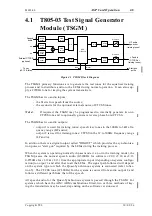
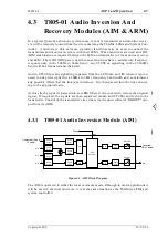
Taking the ICCS input of the TSGM to logic "1" will cause it to generate a keytone
of the correct level. This is detected by the AIM, initiating the inversion/recovery
process and keying the transmitter connected to the ARM. The tone will continue
for as long as the input is at logic "1", and will cease 250ms after the input has
fallen to logic "0" (unless reverse phase burst is selected, in which case the tail time
is 350ms - see Note 3 below). The ICCS inputs to the AIMs are left unconnected.
Note 1:
This method is available with TSGM software v2.12 and later.
2.
An externally generated 2970Hz tone at a level of -23dBm may be added to the
TSGM audio input. This tone is detected by the AIM, initiating the inversion/
recovery process and keying the transmitter connected to the ARM.
Note 2:
For TSGM software versions 2.10 and 2.11 this tone can be mixed with the
audio fed into input 1. For software versions 2.12 and later this tone is fed
separately into input 2.
3.
Taking the ICCS input of the AIM to logic "1" will place it in inversion mode and
the transmitter will be keyed by the associated ARM, independent of the presence
of a 2970Hz tone.
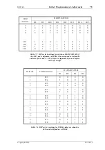
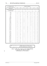
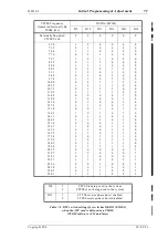
The CTCSS tone from audio output 2 may be generated internally, the frequency being
programmed via DIP switches on the board. Alternatively, the CTCSS may be exter-
nally supplied, but must be passed into the TSGM via input 2 so that it still exits from
audio output 2.
Note 3:
For TSGM software versions 2.12 and later internal CTCSS is generated only
when the ICCS input is at logic "1", and is stopped when the ICCS input
becomes logic "0".
Versions 2.12 and later support reverse phase burst of internal or external
CTCSS, where, after a transition from logic "1" to logic "0" of the ICCS input,
the output phase of the CTCSS is reversed 180 degrees. Use of reverse phase
burst continues CTCSS for 100ms after ICCS falls to logic "0" and continues
the 2970Hz keytone for 250ms after cessation of CTCSS. The use of reverse
phase burst CTCSS is selectable by DIP switch.
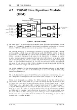
The training sequence is controlled by the System Controller but performed by the
TSGM(s) and LEMs. Each time the training of an LEM begins, the TSGM sends out a
start gun (synchronisation) pulse via its "DIGOUT" output. This is passed to the "GPS"
input of all the LEMs, but only the LEM being trained will respond to it.
There is only one TSGM in a typical network. However, a second one may be added to
serve as a back-up if the other fails (if the TSGM fails, all audio is lost as it is routed
through the TSGM).
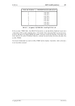
The TSGMs are assigned addresses according to the network to which they are con-
nected (see Table 4.1) and have their RS-485 transceivers permanently enabled for com-
municating with the System Controller.
Summary of Contents for T805
Page 16: ...4 2 ASP Card Operation M805 00 30 04 95 Copyright TEL ...
Page 44: ...7 18 Initial Programming Adjustment M805 00 30 09 96 Copyright TEL ...
Page 70: ...14 1 2 PCB Information M805 00 30 04 95 Copyright TEL ...
Page 89: ...Copyright TEL 30 09 96 M805 00 T805 Front Panel PCB Information 14 5 3 ...


