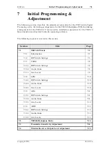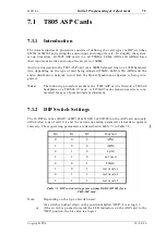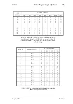
7.10
Initial Programming & Adjustment
M805-00
30/09/96
Copyright TEL
7.1.4
LEM
7.1.4.1
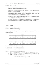
DIP Switch Settings
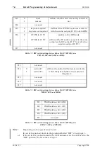
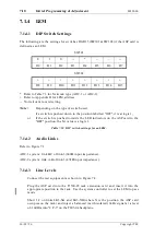
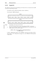
The following are the settings for switches D0-D15 (SW301 & SW302) if the ASP card is
defined as an LEM.
SW301
SW302
* Refer to Table 7.3 for Network type (ADC-1 or ADC-2).
+ Refer to Appendix B for LEM address.
-- Not relevant to card setting.
Note:
Depending on the type of switch used:
if a switch is pushed down in the position labelled "OFF", it is at logic 1;
or
if the switch is pushed towards the LED indicators on the ASP card to the
"OFF" position, the bit value is a logic 1.
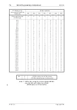
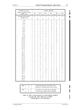
Table 7.10 DIP switch settings for an LEM.
7.1.4.2
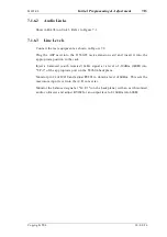
Audio Links
Refer to Figure 7.1.
ADC-1 system: link B-C of link-3 (600
Ω
input impedance).
ADC-2 system: link A-B of link-3 (47k
Ω
input impedance).
7.1.4.3
Line Levels
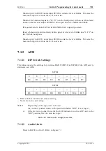
Connect the test equipment as shown in Figure 7.2.
Plug the ASP card into the T1560-05 rack extension card and insert it into the
appropriate position in the rack. Use the system controller to set the LEM to pass
mode.
Short 1-2 on links LK3-XA and LK3-XB (where X is the position the ASP card
occupies on the rack) and inject a balanced (earth isolated) 1kHz signal at a level
of -10dBm into "I/P-3" on the T805-04 backplane.
0
1
0
--
*
--
--
--
D0
D1
D2
D3
D4
D5
D6
D7
+
+
+
+
+
+
+
+
D8
D9
D10
D11
D12
D13
D14
D15
Summary of Contents for T805
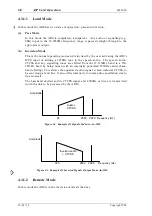
Page 16: ...4 2 ASP Card Operation M805 00 30 04 95 Copyright TEL ...
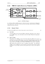
Page 44: ...7 18 Initial Programming Adjustment M805 00 30 09 96 Copyright TEL ...
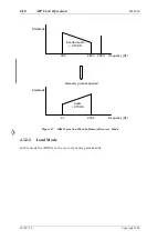
Page 70: ...14 1 2 PCB Information M805 00 30 04 95 Copyright TEL ...
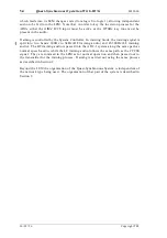
Page 89: ...Copyright TEL 30 09 96 M805 00 T805 Front Panel PCB Information 14 5 3 ...

