7.16
Initial Programming & Adjustment
M805-00
30/09/96
Copyright TEL
7.5
Line Barrier Unit Connection
See also Section 1.3, Warnings.
7.5.1
Introduction
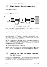
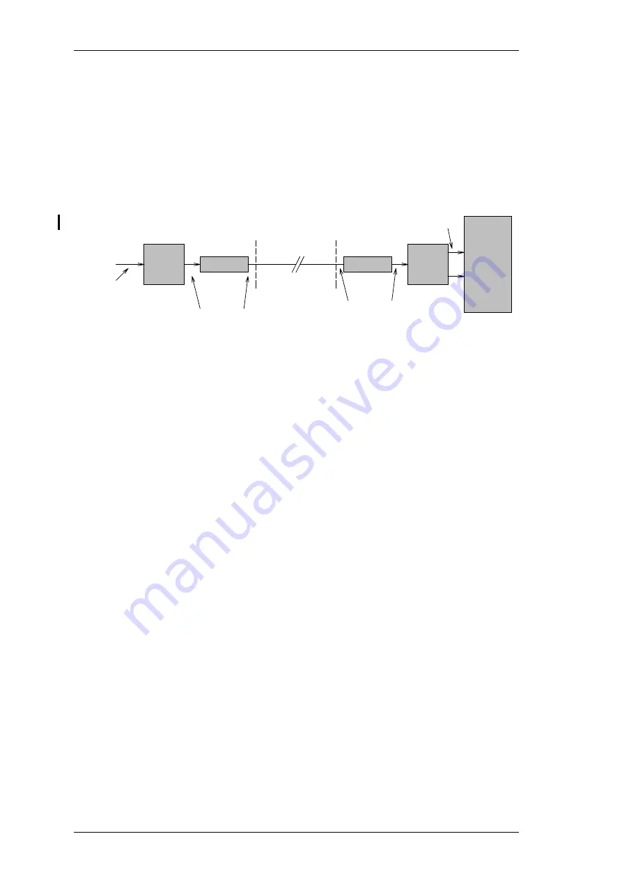
Figure 7.3 AIM/ARM Input And Output Levels
When an AIM/ARM combination is used, both the AIM and ARM must be connected
to the Telecom lines via line barrier units.
These line barrier units must be Telecom approved for the country in which the
T805 system is operated.
In the UK the T805 system is approved for indirect connection into the Telecom speech
band circuits (BS6328). Where signalling is required, a nominal frequency of 2280Hz is
used. It requires no signalling in the frequency range 2220Hz to 2340Hz. No signalling
below 200Hz is presented to the Telecom network.
The T805, as supplied with line barriers, is suitable for direct connection to speech band
circuits or relevant branch systems for speech band circuits. It may be connected to 4W
Private Speech Band circuits. It must be used only in conjunction with the protection
barrier(s) specified in the instructions for use.
The T805 is also suitable for point to point circuits.
The T805 is BABT approved for use only with the CYFAS 88/0507 Line Barrier Units.
Approval will be invalidated unless the T805 is used in conjunction with this barrier.
7.5.2
Wiring Between The Line Barrier Unit And
The T805 System
Connection to the speech band circuit is from the terminal blocks in the CYFAS Line
Barrier Unit (type 88/0507), via cable with solid copper conductors of nominal diameter
between 0.4mm and 0.6mm. Refer to Section 10 for installation details.
AIM
LBU
LBU
ARM
Base Site
equipment
Telecom link
1900Hz at -10dBm
2900Hz at -23dBm
1900Hz at -10dBm
2900Hz at -23dBm
1kHz at -12dbm
1kHz at -10dBm
2970Hz at -23dBm
Summary of Contents for T805
Page 16: ...4 2 ASP Card Operation M805 00 30 04 95 Copyright TEL ...
Page 44: ...7 18 Initial Programming Adjustment M805 00 30 09 96 Copyright TEL ...
Page 70: ...14 1 2 PCB Information M805 00 30 04 95 Copyright TEL ...
Page 89: ...Copyright TEL 30 09 96 M805 00 T805 Front Panel PCB Information 14 5 3 ...


