8.8
Functional Tests
M805-00
30/09/96
Copyright TEL
8.2.3
Test Mode 2
8.2.3.1
Introduction
Remove any shorts from LINK 1.
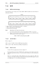
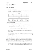
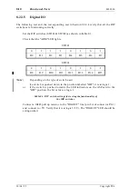
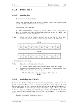
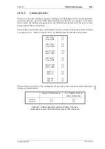
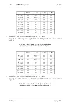
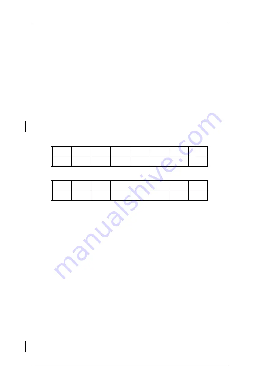
Set the DIP switches (SW301 & SW302) as shown in Table 8.2 (note that only
switches D0, D1 and D2 define the test mode).
Apply power to the ASP card and short LINK 1 after the ASP card has success-
fully powered up.
The "TEST MODE" LED should light up. All other LEDs should be extinguished
(unless otherwise indicated). The operation of the "WDR" LED is random in this
test mode and should be ignored.
SW301
SW302
-- Not relevant to card setting.
Note:
Depending on the type of switch used:
if a switch is pushed down in the position labelled "OFF", it is at logic 1;
or
if the switch is pushed towards the LED indicators on the ASP card to the
"OFF" position, the bit value is a logic 1.
Table 8.2 DIP switch settings for placing the ASP card in test
mode 2.
8.2.3.2
Audio Interface Circuit
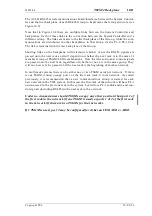
In this test the relays are de-energised, preventing audio output from the AICs reaching
the output connector. A signal is fed into the main input of each audio interface circuit
(AIC), digitised and passed into the digital signal processor IC (DSP). It is then passed
back into the AIC, reconverted into analogue and passed into the AIC's outputs. The
signal path is thus:
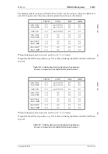
the signal from the summing of inputs 3 and 4 is passed to the balanced output of
IC202, and the input 2 signal is passed to the balanced output of IC204.
Note:
If the audio levels have been set up in test mode 1, they do not need to be
readjusted as described below.
0
1
1
--
--
--
--
--
D0
D1
D2
D3
D4
D5
D6
D7
--
--
--
--
--
--
--
--
D8
D9
D10
D11
D12
D13
D14
D15
Summary of Contents for T805
Page 16: ...4 2 ASP Card Operation M805 00 30 04 95 Copyright TEL ...
Page 44: ...7 18 Initial Programming Adjustment M805 00 30 09 96 Copyright TEL ...
Page 70: ...14 1 2 PCB Information M805 00 30 04 95 Copyright TEL ...
Page 89: ...Copyright TEL 30 09 96 M805 00 T805 Front Panel PCB Information 14 5 3 ...


