M805-00
Functional Tests
8.9
Copyright TEL
30/09/96
•
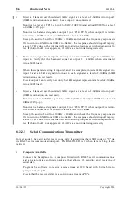
Inject a balanced (earth isolated) 1kHz signal at a level of -10dBm into input 3
(600
Ω
termination on test lead). Leave input 4 unconnected.
Monitor the level at TP13 or pin 26 of AIC-1 (IC210) and adjust RV205 for a level
of 0dBm (2.2V p-p).
Monitor the balanced signal at TP16/TP17 with a high impedance voltmeter or
oscilloscope and check that the level measures 820mV p-p (290mV rms).
Verify that the relays are de-energised by checking there is no signal present at the
output 1 connector (or TP14/TP15).
•
Inject a balanced (earth isolated) 1kHz signal at a level of -10dBm into input 2
(600
Ω
terminations on test lead).
Monitor the level at TP31 or pin 26 of AIC-2 (IC211) and adjust RV203 for a level of
0dBm (2.2V p-p).
Monitor the balanced signal at TP28/TP29 with a high impedance voltmeter or
oscilloscope and check that the level measures 820mV p-p (290mV rms).
Verify that the relays are de-energised by checking there is no signal present at the
output 2 connector (or TP26/TP27).
8.2.3.3
Serial Communications Transmitter
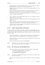
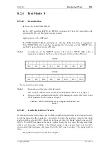
In this test the RS-485 transmitter is disabled (verified by the RS-485 LED being extin-
guished) and the receive mode enabled. If the ASP card is sent the ASCII code for the
symbols "AB", the LEM LED will light up for 300ms every time it receives a correctly
structured signal.
Connect the backplane to a computer fitted with RS-485 serial communications
and an appropriate software package that allows the sending of serial data.
Program the software to transmit a data stream at 1200 baud with 7 data bits, odd
parity and 1 stop bit.
Send the "AB" data stream and observe the LEM LED.
Note:
If a framing, overrun or parity error occurs, the TSGM LED will light and
stay lit until the card is reset or powered down.
8.2.3.4
Reset Circuitry And Watchdog Timer
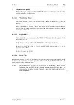
Enable the watchdog timer by removing the short on "LINK 1" and check that:
- the TSGM and LEM LEDs flash every 500msec.;
- the test mode LED lights and stays lit;
- the "AIM" LED does not light at all.
Note:
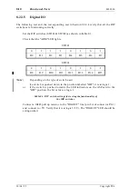
The status of the ARM LED depends on the setting of the DIP switches
(refer to Section 8.2.2.5).
When this test is complete, replace the short on "LINK 1" to disable the watchdog
timer.
Summary of Contents for T805
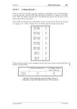
Page 16: ...4 2 ASP Card Operation M805 00 30 04 95 Copyright TEL ...
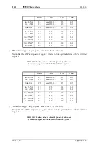
Page 44: ...7 18 Initial Programming Adjustment M805 00 30 09 96 Copyright TEL ...
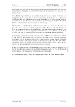
Page 70: ...14 1 2 PCB Information M805 00 30 04 95 Copyright TEL ...
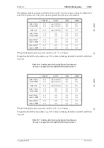
Page 89: ...Copyright TEL 30 09 96 M805 00 T805 Front Panel PCB Information 14 5 3 ...


