M805-00
Fault Finding
9.13
Copyright TEL
30/09/96
9.4.9
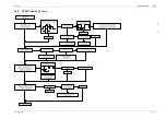
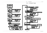
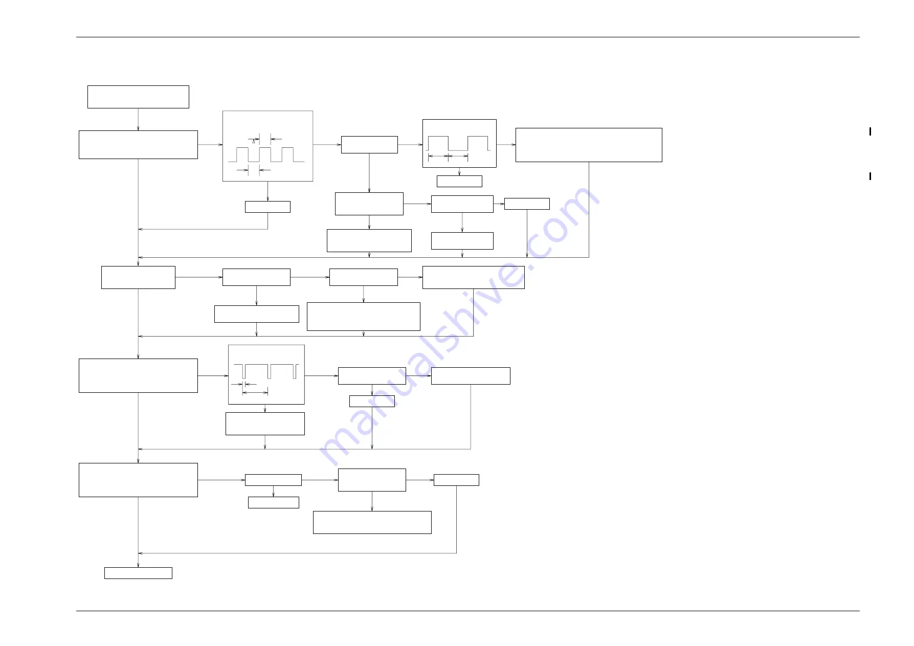
T805 Watchdog Timer
Power up the ASP card in test mode 1.
Remove the short on link-1.
Do the DIGOUT, RS-485 and
WD LEDs flash?
Check for shorts or missing
components around relevant
circuitry.
Place a short on link 1.
Do the DIGOUT and RS-485
LEDs light and stay lit?
Check pin 13 of IC120.
Is it at logic 1?
Check pin 8 of IC124.
Is it at logic 1?
Replace IC120, 124 if necessary.
Check for shorts.
Replace IC124 if necessary.
Check pin 12 of IC107. Is the
waveform as shown below?
Set the DIP switches for test mode 3
and remove the short from link 1.
Is the test mode LED lit and the TSGM,
LEM, AIM, ARM, RS-485 and
DIGOUT LEDs extinguished?
Check pin 3 of IC107.
Is it at logic 0?
Check the DSP for faults.
Check the AIC for faults
Check the DSP is OK.
Check circuitry leading to
pin 12 of IC107.
Press the reset switch.
Do the LEDs flash then stabilise with
the TEST MODE LED lit and the TSGM,
LEM, AIM, ARM, RS-486 and DIGOUT
LEDs extinguished?
Is the switch OK?
Y
Y
N
Y
N
N
N
Y
Y
N
N
Y
Y
N
Y
Y
N
N
N
Y
N
Y
N
Y
Y
N
N
Y
500ms
500ms
Is pin 3 of IC107 oscillating
as shown below?
Check the square wave follows through the
IC124 invertor (pin 13,12), the IC120 NAND
gate (pin 12,11) and the IC124 invertor
pins 9,8). If all OK then check the low voltage
reset IC (IC108). Replace any if necessary.
Y
N
Check for overheating components
and short circuits.
Replace if necessary.
Look at pin 9 of IC107. Does the wave-
form appear similiar to the one below?
Is pin 12 of IC107
at logic 0 (0V)?
Replace IC107.
Replace IC107.
Is the voltage on
pin 2 of IC120 greater
than 2.4V?
Is voltage on pin 1
of IC120 at +5V?
Replace IC120.
Check DSP is
operating correctly.
Check pin 12 of IC124.
Is it at logic 1 (5V)?
Check the low voltage reset (IC108).
Check R108, R109.
Check the 5V rail.
Replace IC108 if necessary.
Replace IC107.
5µs
44µs
Check pin 2 of IC120.
Does it go to 0V when
switch is pushed?
Replace IC120.
Replace switch.
Check components around pin 2
of IC120 for dry joints, shorts, etc.
Replace if necessary.
Watchdog circuitry OK.
30µs
30µs
Summary of Contents for T805
Page 16: ...4 2 ASP Card Operation M805 00 30 04 95 Copyright TEL ...
Page 44: ...7 18 Initial Programming Adjustment M805 00 30 09 96 Copyright TEL ...
Page 70: ...14 1 2 PCB Information M805 00 30 04 95 Copyright TEL ...
Page 89: ...Copyright TEL 30 09 96 M805 00 T805 Front Panel PCB Information 14 5 3 ...

