10.14
T805-04 Backplane
M805-00
30/04/95
Copyright TEL
10.3.2.4
Linking Details For The Test Receiver (Multi-rack
Systems)
(a)
Test Receiver Feeding A Single LEM
The signal from a test receiver always feeds into the high impedance input (47k
Ω
)
of the ASP card, input 2. The required terminating impedance of 600 ohms is
linked in on the backplane.
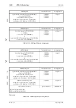
When a receiver is connected to a single LEM, link in the terminating resistance of
600 ohms by shorting positions 1-2 of link LK2-X, where X is the port position of
the card on the backplane (X ranges between 1 & 9).
Short position 2-3 of links LK2-XA, LK2-XB (open circuits) to prevent the received
signals from being passed on to any other LEMs.
(b)
Test Receiver Feeding Multiple LEMs
When a receiver is to feed more than one LEM, the procedure is similar to that
described in Section 10.3.1.3 (b), the only difference being that the monitor
receiver audio may have to be passed onto the next backplane in the series. As
before, the LEMs must be placed consecutively, with this trend being continued
onto the next rack.
If the monitor receiver audio is being passed from rack "i" to rack "i+1", short posi-
tions 2-3 of links LK2-0A & LK2-0B of rack "i+1" to
enable
the audio to be fed into
that rack. Otherwise, short positions 1-2 of link LK2-0A & LK2-0B on rack "i+1" to
prevent
the audio being passed on from rack "i".
Example
The monitor receiver feeds audio to LEMs 7, 8 and 9 of rack-2 and
LEMs 1, 2 and 3 of rack-3.
Rack-2 linking details:
Audio from the monitor receiver will be fed into LEM-7 via connec-
tor CN7-1 (input 2 of port 7) and is terminated into 600 ohms by
shorting position 1-2 of LK2-7.
Short position 2-3 of links LK2-8 and LK2-9 (open circuit) since the
600
Ω
termination is provided by LEM-7 position.
Audio is passed from LEM-7 to LEM-8 by shorting position 1-2 on
links LK2-7A & LK2-7B, and from LEM-8 to LEM-9 by shorting
position 1-2 on links LK2-8A & LK2-8B.
The audio is then passed from rack-2 to rack-3 by shorting position
1-2 on the final links in the series, LK2-9A & LK2-9B.
Rack-3 linking details for example:
The audio is buffered and fed from PL-3 on rack-2 into PL-1 on
rack-3. It is then passed to LEM-1 by linking position 2-3 of links
LK2-0A & LK2-0B.
Short positions 1-2 of links LK2-1A & LK2-1B to pass the signal
Summary of Contents for T805
Page 16: ...4 2 ASP Card Operation M805 00 30 04 95 Copyright TEL ...
Page 44: ...7 18 Initial Programming Adjustment M805 00 30 09 96 Copyright TEL ...
Page 70: ...14 1 2 PCB Information M805 00 30 04 95 Copyright TEL ...
Page 89: ...Copyright TEL 30 09 96 M805 00 T805 Front Panel PCB Information 14 5 3 ...


