TM8100/TM8200 Service Manual
Disassembly and Reassembly
135
© Tait Electronics Limited
June 2006
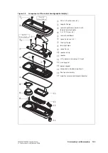
Figure 5.4
Components of the main-board assembly
B
M3x10 screw (x3)
H
D-range screwlock fastener (2x)
C
50W/40W radios:
M2.2x10 PT screw (x2)
25W radios:
K30x8 PT screw (x2)
I
power connector seal
J
power connector
1)
gap pad (50W/40W radio only)
D
auxiliary connector
1!
RF connector nut
E
inner foam D-range seal
1@
RF connector lock washer
F
heat-transfer block
1#
RF connector
G
outer foam seal
1$
main board
H
1$
E
G
F
I
1#
1@
D
J
thermal
paste
3631z_01
1)
9/16 inch (14mm)
15lb·in (1.7N·m)
3/16 inch (5mm)
8lb·in (0.9N·m)
Torx T6
1lb·in (0.11N·m)
Torx T10
15lb·in (1.7N·m)
C
x2
Torx T10
3lb·in (0.34N·m)
1!
B
x3
Summary of Contents for TM8235
Page 1: ...TM8100 mobiles TM8200 mobiles Service Manual MMA 00005 04 Issue 4 June 2006...
Page 10: ...10 TM8100 TM8200 Service Manual Tait Electronics Limited June 2006...
Page 62: ...62 Description TM8100 TM8200 Service Manual Tait Electronics Limited June 2006...
Page 148: ...148 Disassembly and Reassembly TM8100 TM8200 Service Manual Tait Electronics Limited June 2006...
Page 162: ...162 Servicing Procedures TM8100 TM8200 Service Manual Tait Electronics Limited June 2006...
Page 178: ...178 Interface Fault Finding TM8100 TM8200 Service Manual Tait Electronics Limited June 2006...
Page 258: ...258 Receiver Fault Finding TM8100 TM8200 Service Manual Tait Electronics Limited June 2006...
Page 446: ...446 Spare Parts TM8100 TM8200 Service Manual Tait Electronics Limited June 2006...

