82
Circuit Descriptions
TM8100/TM8200 Service Manual
© Tait Electronics Limited
June 2006
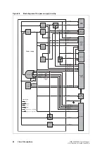
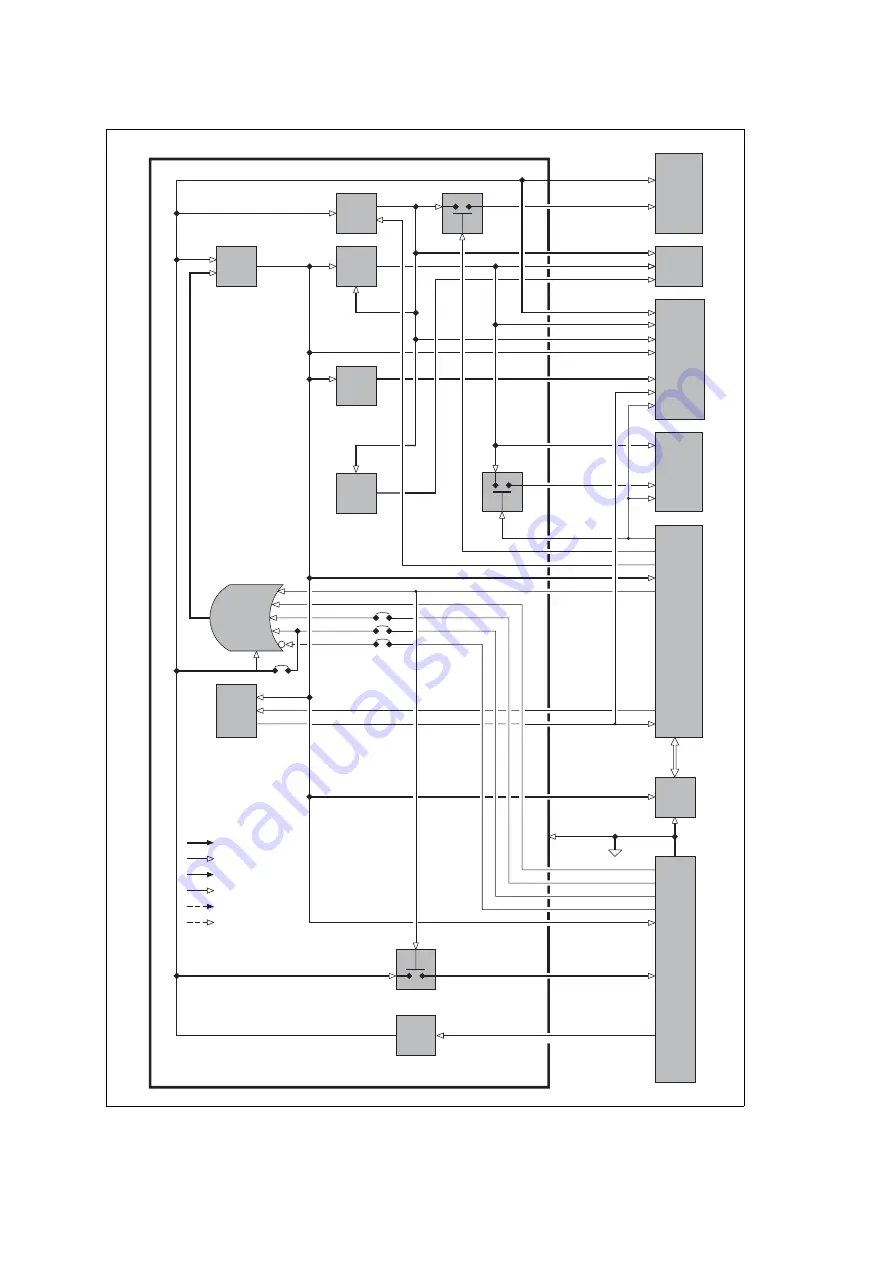
Figure 3.8
Block diagram of the power supply circuitry
Power Supply
Trans-
mitter
Frequency
Synthesizer
CODEC
and
Audio
Receiver
Digital
Board
Debug
Connector
Interface
SMPS
3 V
Regulator
9 V
Regulator
9 V Tx Switch
+3V3
2V5
Regulator
3 V Rx
Switch
PSU
Super-
visor
13V8 Switch
Reverse
Polarity
Protection
+13V8 BATT
+9V0 TX
+9V0
+3V0 AN
+13V8 BATT
+9V0
+3V0 AN
+3V3
+2V5 CDC
+3V0 AN
+3V0 RX
DIG RX EN
DIG TX EN
DIG SLP EN
+3V3
DIG PSU LATCH
DIG WD KICK
PSU SYS RST
+3V3
AGND
CH ON OFF
AUX GPI3
AUX GPI2
ITF IOP GPIO7
+3V3
+13V8 SW
+13V8 BATT
OR Gate
Hardware
Links
IOP PWR SENSE
IGNITION SENSE
EMERGENCY
+9V0
6V0
Regulator
+6V0
13V8 PWR
SENSE
Signal Types:
RF
analog
clock
digital
asynchronous serial data
synchronous serial data
Summary of Contents for TM8235
Page 1: ...TM8100 mobiles TM8200 mobiles Service Manual MMA 00005 04 Issue 4 June 2006...
Page 10: ...10 TM8100 TM8200 Service Manual Tait Electronics Limited June 2006...
Page 62: ...62 Description TM8100 TM8200 Service Manual Tait Electronics Limited June 2006...
Page 148: ...148 Disassembly and Reassembly TM8100 TM8200 Service Manual Tait Electronics Limited June 2006...
Page 162: ...162 Servicing Procedures TM8100 TM8200 Service Manual Tait Electronics Limited June 2006...
Page 178: ...178 Interface Fault Finding TM8100 TM8200 Service Manual Tait Electronics Limited June 2006...
Page 258: ...258 Receiver Fault Finding TM8100 TM8200 Service Manual Tait Electronics Limited June 2006...
Page 446: ...446 Spare Parts TM8100 TM8200 Service Manual Tait Electronics Limited June 2006...


