84
Circuit Descriptions
TM8100/TM8200 Service Manual
© Tait Electronics Limited
June 2006
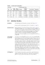
shows the configuration of the hardware links LK1, LK2 and LK4
for the individual power-sense options. It also lists the dependence of the
power-sense options with respect to the GPI lines, which can or cannot be
used.
shows the configuration of ‘emergency power sense’. ‘Emergency
power sense’ can be configured with any of the above power sense options.
Table 3.1
Configuration of hardware links and GPI lines for power-sense options
Power-sense option
Links
required
Configuration of remaining links and
use of AUX GPI3 and IOP GPIO7
Voltages
required
13.8V battery power
sense
LK1 in
LK2 in:
AUX GPI3 must be left floating.
10.8V
≤
supply
≤
16V
LK2 out:
AUX GPI3 can be used as GPI
a
.
LK4 out
IOP GPIO7 can be used as GPIO.
auxiliary power sense
(ignition sense)
LK2 in
LK1 in:
Input line must sink >1mA from
AUX GPI3 (which is pulled to 13.8V by a
33k
Ω
resistor). The impedance between
the vehicle ignition signal and ground
must be
≤
1k
Ω
.
AUX GPI3
≤
0.7V off
AUX GPI3
≥
2.6V high (active)
ignition-sense tolerant to
3.3V, 5V and 12V
LK1 out:
Input line must be active high
b
.
LK4 out
IOP GPIO7 can be used as GPIO.
internal power sense
LK1 out
IOP GPIO7
≤
0.7V off
IOP GPIO7
≥
2.6V high
(active)
ignition-sense tolerant to
3.3V and 5V only
LK2 out
AUX GPI3 can be used as GPI.
LK4 in
With LK4 in, the input line must be active
high
c
.
no power sense
LK1 out
10.8V
≤
supply
≤
16V
LK2 out
AUX GPI3 can be used as GPI.
LK4 out
IOP GPIO7 can be used as GPIO.
a. If LK2 is out and AUX GPIO is not used, R775 (33k) should be placed to ensure that AUX GPI3 does not float
(R775 is not placed by factory default).
b. If LK1 is out and R775 is placed, AUX GPI3 should be driven low as well.
c. If LK 4 is in and R723 is placed, IOP GPIO7 should be driven low as well. (R723 is placed by factory default.)
Table 3.2
Configuration of hardware link LK3 and AUX GPI2 for ‘emergency power sense’
External push-button
or toggle switch
required to enter
emergency mode
Links
required
Implications on AUX GPI2
Voltages required
Yes
LK3 in
AUX GPI2 must be connected to an
external (hidden) push-button or toggle
switch, which connects it to ground.
≤
0.7V active,
floating inactive
No
LK3 in
AUX GPI2 must be left floating
LK3 out
AUX GPI2 can be used as GPI.
Summary of Contents for TM8235
Page 1: ...TM8100 mobiles TM8200 mobiles Service Manual MMA 00005 04 Issue 4 June 2006...
Page 10: ...10 TM8100 TM8200 Service Manual Tait Electronics Limited June 2006...
Page 62: ...62 Description TM8100 TM8200 Service Manual Tait Electronics Limited June 2006...
Page 148: ...148 Disassembly and Reassembly TM8100 TM8200 Service Manual Tait Electronics Limited June 2006...
Page 162: ...162 Servicing Procedures TM8100 TM8200 Service Manual Tait Electronics Limited June 2006...
Page 178: ...178 Interface Fault Finding TM8100 TM8200 Service Manual Tait Electronics Limited June 2006...
Page 258: ...258 Receiver Fault Finding TM8100 TM8200 Service Manual Tait Electronics Limited June 2006...
Page 446: ...446 Spare Parts TM8100 TM8200 Service Manual Tait Electronics Limited June 2006...


