TM8100/TM8200 Service Manual
General Information
111
© Tait Electronics Limited
June 2006
4.4
Test Equipment Setup
Introduction
This section covers the setting up of the test equipment for servicing the
radios, as well as related aspects:
■
setting up of test equipment, including test unit
■
basic programming and calibration tasks
■
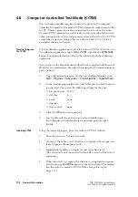
invoking CCTM (computer-controlled test mode)
■
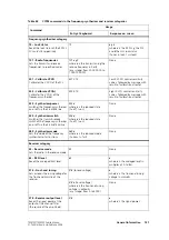
summary tables of CCTM commands and error codes
■
visual and audible indications provided by radio
The last-named aspect applies to control heads with UI, and concerns the
STATUS
LEDs and LCD screen, and the various alerts and confidence tones
emitted from the speaker.
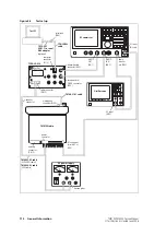
Connect Equipment
Connect the test equipment to the radio as shown in
. Use the test
unit, cables and adaptor of the service kit. Refer to
for details of the test equipment and service kit.
The test unit is described in
“TOPA-SV-024 Test Unit” on page 571
For testing receive and transmit functions respectively, the switches of the
test unit must be set as described below. (When programming or calibrating
radios the switches have no effect, although it is good practice to set the
MODE
switch to
“R
X
”
.)
Settings for
Receive Tests
For receive tests set the switches on the test unit as follows:
■
HOOK
switch
:
“O
FF
H
OOK
”
■
MODE
switch
:
“R
X
”
■
AUDIO
IN
switch :
“O
FF
”
■
AUDIO
OUT
switch:
“S
PEAKER
”
or
“L
OAD
”.
In the last-named case, with the switch in the
“S
PEAKER
”
position, the
received audio is output from the test unit’s speaker. In the
“L
OAD
”
position a
16
Ω
load is switched into the circuit in place of the test unit’s speaker.
Note, however, that the
AUDIO
OUT
switch has no effect on the radio’s speaker.
Settings for
Transmit Tests
For transmit tests set the switches on the test unit as follows:
■
HOOK
switch
:
“O
FF
H
OOK
”
■
MODE
switch
:
“R
X
”
initially
■
AUDIO
IN
switch :
“M
IC
A
UDIO
”
■
AUDIO
OUT
switch: (immaterial).
When ready to transmit, set the
MODE
switch to the
“T
X
/PTT”
position.
This switch functions in the same way as the PTT switch on the
microphone.
Product Support CD
Install the programming and calibration applications on the test PC.
These applications are included on the product support CD supplied with
the service kit.
Summary of Contents for TM8235
Page 1: ...TM8100 mobiles TM8200 mobiles Service Manual MMA 00005 04 Issue 4 June 2006...
Page 10: ...10 TM8100 TM8200 Service Manual Tait Electronics Limited June 2006...
Page 62: ...62 Description TM8100 TM8200 Service Manual Tait Electronics Limited June 2006...
Page 148: ...148 Disassembly and Reassembly TM8100 TM8200 Service Manual Tait Electronics Limited June 2006...
Page 162: ...162 Servicing Procedures TM8100 TM8200 Service Manual Tait Electronics Limited June 2006...
Page 178: ...178 Interface Fault Finding TM8100 TM8200 Service Manual Tait Electronics Limited June 2006...
Page 258: ...258 Receiver Fault Finding TM8100 TM8200 Service Manual Tait Electronics Limited June 2006...
Page 446: ...446 Spare Parts TM8100 TM8200 Service Manual Tait Electronics Limited June 2006...


