370
Transmitter Fault Finding (25W)
TM8100/TM8200 Service Manual
© Tait Electronics Limited
June 2006
Task 29 —
Check Power at
Directional Coupler
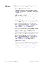
, there is no fault in the initial RF
signal path, investigate the final signal path. This part of the circuitry may
also require investigation following certain checks in
. Begin by checking the directional coupler as follows:
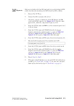
1.
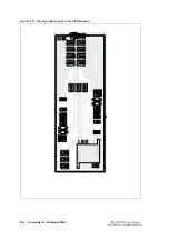
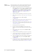
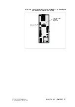
If not already done, remove the
DIRC
TOP
can.
2.
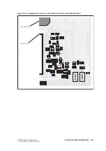
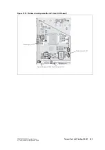
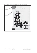
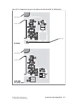
Remove the coupling capacitors
C348
,
C349
,
C350
(see
).
3.
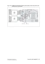
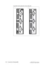
Solder one terminal of a test capacitor to the PCB at the point shown
in
. Mount the capacitor vertically. Use a test capacitor
of the type GRM111, DLI C17, Murata 1210, or the equivalent.
The value of the capacitor depends on the frequency band of
the radio:
■
A4 — 100pF
■
B1, C0, D1 — 680pF
■
H5, H6 — 82pF.
4.
Solder a 50
Ω
test lead to the PCB. Solder the outer sheath in the
position shown in
, and solder the central wire to the
other terminal of the test capacitor.
5.
Connect the test lead to the test set.
6.
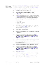
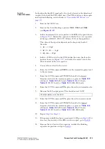
Enter the CCTM command
326 5
to set the transmitter power level
to the maximum.
7.
Enter the CCTM command
101
x x
0
, where
x
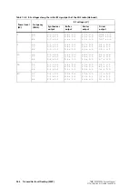
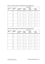
is the lowest
frequency (in hertz) for maximum power, as given in
(A4),
(B1),
(D1) or
(H5, H6).
8.
Enter the CCTM command
33
to place the radio in transmit mode.
9.
Measure the RF output power. This should exceed 35W.
10.
Enter the CCTM command
32
to place the radio in receive mode.
11.
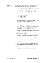
Enter the CCTM command
101
x x
0
, where
x
is the highest
frequency (in hertz) for maximum power, as given in
(A4),
(B1),
(D1) or
(H5, H6).
12.
Repeat
to
13.
If the power measured in both the above cases exceeds 35W, go to
. If it does not, go to
14.
Remove the test lead and test capacitor, resolder the coupling
capacitors in position, and go to
.
RF output power: more than 35W
Summary of Contents for TM8235
Page 1: ...TM8100 mobiles TM8200 mobiles Service Manual MMA 00005 04 Issue 4 June 2006...
Page 10: ...10 TM8100 TM8200 Service Manual Tait Electronics Limited June 2006...
Page 62: ...62 Description TM8100 TM8200 Service Manual Tait Electronics Limited June 2006...
Page 148: ...148 Disassembly and Reassembly TM8100 TM8200 Service Manual Tait Electronics Limited June 2006...
Page 162: ...162 Servicing Procedures TM8100 TM8200 Service Manual Tait Electronics Limited June 2006...
Page 178: ...178 Interface Fault Finding TM8100 TM8200 Service Manual Tait Electronics Limited June 2006...
Page 258: ...258 Receiver Fault Finding TM8100 TM8200 Service Manual Tait Electronics Limited June 2006...
Page 446: ...446 Spare Parts TM8100 TM8200 Service Manual Tait Electronics Limited June 2006...

