24
Installing a Dual-Radio System
TM8260 Installation and Programming Guide
© Tait Limited
October 2014
Detailed Steps
1.
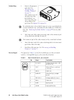
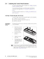
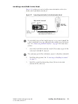
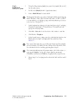
Remove all appropriate
grommets. See
“Removing and
Installing Grommets”
on page 15
The outermost port of
the radio body with
link J4 fitted is not
used. Leave the grom-
met installed in this
port (item
g
If a radio body does not have link J4 removed, or you cannot identify the
correct radio body to use, you will need to disassemble one or both inter-
faces. See
“Removing the Body Interface” on page 22
for more infor-
mation.
2.
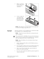
Attach one end of the radio connecting cable to the outermost port
of the radio body with link J4 removed.
The innermost port of this radio connects to the control head solution.
3.
Attach the other end of the radio connecting cable to the innermost
port of the other radio body.
4.
Install the cable grommets. See
Pins and Signals
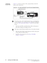
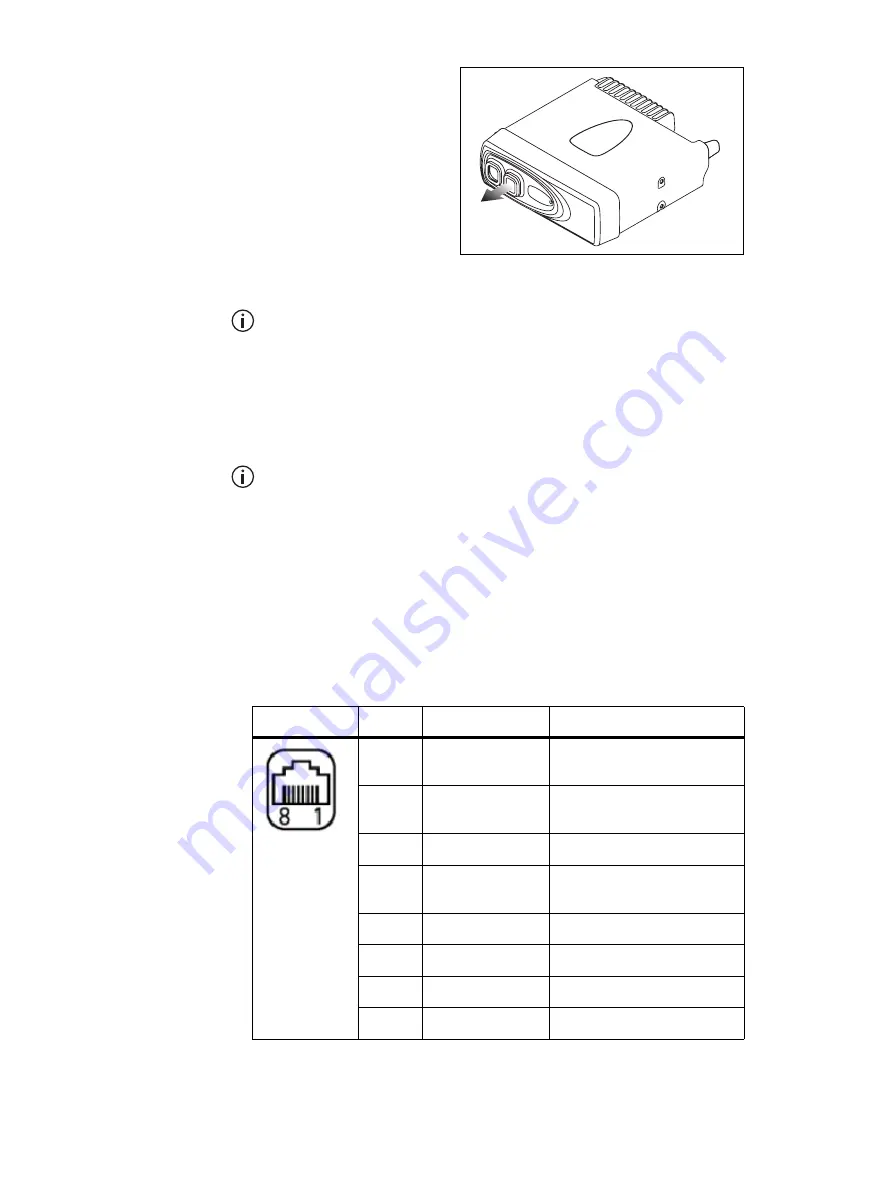
The pinouts in
are for the two RJ45 ports on the radio body
interface, and single RJ45 port on the control head interface.
Table 3.1
Remote interface ports—pins and signals
Pin
Name
Description
1
RX_AUDIO
Analogue receive audio – after
volume control.
2
13V8
Default setting is a switched
+13V8 line.
3
RS485+
RS485 data.
4
AGND/PTT
Default setting is analogue
ground.
5
MIC AUDIO
Analogue electret mic input.
6
RS485
RS485 data.
7
DGND
Digital ground.
8
ON/OFF
Radio on/off control.
front view


