208
Frequency Synthesizer Fault Finding
TM9100 Service Manual
© Tait Electronics Limited
August 2005
Task 28 —
Check VCO
Check that the correct receive and transmit frequencies are synthesized.
The receive frequency is that of the VCO output
SYN
RX
LO
1
at the
RX
port
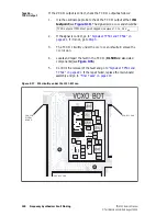
shown in
Figure 9.12
. The transmit frequency is that of the output
SYN
TX
LO
at the
TX
port.
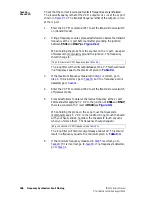
1.
Enter the CCTM command
335 1
to set the transmit-receive switch
on (transmit mode).
2.
Using a frequency counter, proceed as follows to observe the transmit
frequency at the
TX
port before and after grounding the junction
between C541 and R547 (see
Figure 9.12
):
While holding the probe from the counter on the
TX
port, use a pair
of tweezers to momentarily ground the junction. The frequency
should change to:
The loop filter will hold its output steady at 13.3 V. This should result
in a frequency equal to the maximum given in
Table 9.4
.
3.
If the maximum frequency measured in
Step 2
is correct, go to
Step 4
. If it is incorrect, go to
Task 30
, but if no frequency at all is
detected, go to
Task 31
.
4.
Enter the CCTM command
335 0
to set the transmit-receive switch
off (receive mode).
5.
Proceed as follows to observe the receive frequency at the
RX
port
before and after applying 3 V DC to the junction of C541 and R547;
there is a convenient 3 V level at R544 (see
Figure 9.9
):
While holding the probe on the
RX
port, use the tweezers to
momentarily apply 3 V DC to the junction; do not touch the board
with your hand, and do not allow the tweezers to touch any cans
when you remove them. The frequency should change to:
The loop filter will hold its output steady at about 0V. This should
result in a frequency equal to the minimum given in
Table 9.4
.
6.
If the minimum frequency measured in
Step 5
is correct, go to
Task 29
. If it is incorrect, go to
Task 30
. If no frequency is detected,
go to
Task 31
.
TX port: maximum VCO frequency (see
Table 9.4
)
RX port: minimum VCO frequency (see
Table 9.4
)
Summary of Contents for TM9100
Page 1: ...TM9100 mobiles Service Manual MMA 00017 01 Issue 1 August 2005 ...
Page 4: ...4 TM9100 Service Manual Tait Electronics Limited August 2005 ...
Page 10: ...10 TM9100 Service Manual Tait Electronics Limited August 2005 ...
Page 22: ...22 Introduction TM9100 Service Manual Tait Electronics Limited August 2005 ...
Page 62: ...62 Description TM9100 Service Manual Tait Electronics Limited August 2005 ...
Page 96: ...96 TM9100 Service Manual Tait Electronics Limited August 2005 ...
Page 138: ...138 Disassembly and Reassembly TM9100 Service Manual Tait Electronics Limited August 2005 ...
Page 152: ...152 Servicing Procedures TM9100 Service Manual Tait Electronics Limited August 2005 ...
Page 168: ...168 Interface Fault Finding TM9100 Service Manual Tait Electronics Limited August 2005 ...
Page 244: ...244 Receiver Fault Finding TM9100 Service Manual Tait Electronics Limited August 2005 ...
Page 396: ...396 CODEC and Audio Fault Finding TM9100 Service Manual Tait Electronics Limited August 2005 ...
Page 420: ...420 Fault Finding of Control Head TM9100 Service Manual Tait Electronics Limited August 2005 ...
Page 426: ...426 Spare Parts TM9100 Service Manual Tait Electronics Limited August 2005 ...
Page 430: ...430 TM9100 Service Manual Tait Electronics Limited August 2005 ...
Page 444: ...444 TMAA04 05 Ignition Sense Kit TM9100 Service Manual Tait Electronics Limited August 2005 ...
Page 448: ...448 TMAA10 01 Desktop Microphone TM9100 Service Manual Tait Electronics Limited August 2005 ...


