50
Description
TM9100 Service Manual
© Tait Electronics Limited
August 2005
2.5.1
RF Hardware
PIN Switch
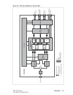
The RF PIN switch circuitry selects the RF path to and from the antenna
to either the Tx or Rx circuitry of the radio. In addition to the switching
functionality, the PIN switch is used to provide attenuation to the Rx front
end in high signal-strength locations.
Front End and
First IF
The front-end hardware amplifies and image-filters the received RF
spectrum, then down-converts the desired channel frequency to a first
intermediate frequency IF1 of 45.1 MHz (UHF) or 21.4 MHz (VHF) where
coarse channel filtering is performed. The first LO signal is obtained from
the frequency synthesizer and is injected on the low side of the desired
channel frequency for all bands. In receive mode, the modulation to the
frequency synthesizer is muted. See
“Frequency Synthesizer” on page 57
for
a description of the frequency synthesizer. The output of the first IF is then
down-converted using an image-reject mixer to a low IF of 64kHz.
Quadrature
Demodulator
The LO for the image-reject mixer (quadrature demodulator) is synthesized
and uses the TCXO as a reference. This ensures good centring of the IF
filters and more consistent group-delay performance. The quadrature
demodulator device has an internal frequency division of 2 so the second
LO operates at 2 x (IF1 + 64 kHz). The quadrature output from this mixer is
fed to a pair of ADCs with high dynamic range where it is oversampled at
256kHz and fed to the custom logic device.
Automatic Gain
Control
The AGC is used to limit the maximum signal level applied to the image-
reject mixer and ADCs in order to meet the requirements for
intermodulation and selectivity performance. Hardware gain control is
performed by a variable gain amplifier within the quadrature demodulator
device driven by a 10-bit DAC. Information about the signal level is
obtained from the IQ data output stream from the ADCs. The control loop
is completed within the custom logic. The AGC will begin to reduce gain
when the combined signal power of the wanted signal and first adjacent
channels is greater than about -70dBm. In the presence of a strong adjacent-
channel signal it is therefore possible that the AGC may start acting when
the wanted signal is well below -70dBm.
Noise Blanking
(B1 band only)
With the B1 band, a noise blanker can be selected to remove common
sources of electrical interference such as vehicle ignition noise. The noise
blanker functions by sampling the RF input to the receiver for impulse noise
and momentarily disconnecting the first LO for the duration of the impulse.
The response time of the noise blanker is very fast (tens of nanoseconds) and
is quicker than the time taken for the RF signal to pass through the front-
end hardware, so that the LO is disabled before the impulse reaches the IF
stage where it could cause crystal filter ring.
Summary of Contents for TM9100
Page 1: ...TM9100 mobiles Service Manual MMA 00017 01 Issue 1 August 2005 ...
Page 4: ...4 TM9100 Service Manual Tait Electronics Limited August 2005 ...
Page 10: ...10 TM9100 Service Manual Tait Electronics Limited August 2005 ...
Page 22: ...22 Introduction TM9100 Service Manual Tait Electronics Limited August 2005 ...
Page 62: ...62 Description TM9100 Service Manual Tait Electronics Limited August 2005 ...
Page 96: ...96 TM9100 Service Manual Tait Electronics Limited August 2005 ...
Page 138: ...138 Disassembly and Reassembly TM9100 Service Manual Tait Electronics Limited August 2005 ...
Page 152: ...152 Servicing Procedures TM9100 Service Manual Tait Electronics Limited August 2005 ...
Page 168: ...168 Interface Fault Finding TM9100 Service Manual Tait Electronics Limited August 2005 ...
Page 244: ...244 Receiver Fault Finding TM9100 Service Manual Tait Electronics Limited August 2005 ...
Page 396: ...396 CODEC and Audio Fault Finding TM9100 Service Manual Tait Electronics Limited August 2005 ...
Page 420: ...420 Fault Finding of Control Head TM9100 Service Manual Tait Electronics Limited August 2005 ...
Page 426: ...426 Spare Parts TM9100 Service Manual Tait Electronics Limited August 2005 ...
Page 430: ...430 TM9100 Service Manual Tait Electronics Limited August 2005 ...
Page 444: ...444 TMAA04 05 Ignition Sense Kit TM9100 Service Manual Tait Electronics Limited August 2005 ...
Page 448: ...448 TMAA10 01 Desktop Microphone TM9100 Service Manual Tait Electronics Limited August 2005 ...


