92
Circuit Descriptions
TM9100 Service Manual
© Tait Electronics Limited
August 2005
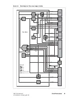
Power Supply
A 3.3 V regulator (U1) converts the switched 13.8V supply from the radio
body to 3.3 V. A 1.5 V regulator (U203) converts the 3.3 V to 1.5V.
A power-sense module (U202) verifies the outputs of the voltage regulators
and—in the case of a fault—creates a power reset signal which is processed
by the FPGA.
Volume Control
The voltage level of the volume control potentiometer is converted to a
digital signal by an analog/digital converter (U601), processed by the FPGA
and transmitted to the radio body.
Main Keypad
The eight keys of the main keypad (function, scroll and selection keys) are
connected to the FPGA by an array of 3 columns and 3 rows. During idle
operation, the
KEY ROW
signals are driven low by the FPGA and the
KEY COL
signals (pulled high by an external resistor) are monitored for activity by the
FPGA. A key-press will generate a high-to-low transition on the associated
column
KEY COL
signal. This, in turn, will initiate a sequence of high output
levels on the
KEY ROW
signals to identify which key was pressed.
LCD Module
The LCD module is connected to the control-head board via the LCD
connector. The LCD module display is controlled by a serial data link to the
FPGA. The backlighting and the optional heating element incorporated in
the LCD module are controlled by a data line each from the FPGA, which
switch two transistors on MOSFET Q102. A temperature signal from the
LCD module is converted to a digital signal by an analog/digital converter
(U601) and processed by the FPGA.
Function Key LEDs
and Status LEDs
The function key LEDs (
F1
and
F4
) and the red, green and amber status
LEDs each are controlled by an FPGA signal and a transistor (Q604 to
Q608). The brightness level is controlled by two FPGA signals, resulting in
four intensity levels (off, low, medium and high).
Keypad
Backlighting
The keypad backlighting LEDs are controlled by two FPGA signals and two
transistors (Q2), resulting in four intensity levels (off, low, medium and
high). The keypad backlighting LEDs are arranged in two groups for the
main keypad and one group for the power button keypad, each group
consisting of three LEDs.
Speaker
The two speaker lines (SPK+ and SPK–) are connected to the speaker
connector (J104) which is joined to the control-head connector (J103)
through two ferrite beads (L105 and L106).
Microphone and
Concealed
Microphone
The audio signals from the microphone connector or the soldering pads of
the concealed microphone are routed to a switching and pre-amplifier
circuit. If a dynamic microphone is required, the pre-amplifier is engaged.
The switching logic is used to select either the standard microphone input
or the concealed microphone signal. The dynamic microphone must be
activated in the programming software.
PTT
The PTT signal from the microphone connector is connected to the FPGA
via a resistor (R25) and relayed to the radio as a digital command.
Summary of Contents for TM9100
Page 1: ...TM9100 mobiles Service Manual MMA 00017 01 Issue 1 August 2005 ...
Page 4: ...4 TM9100 Service Manual Tait Electronics Limited August 2005 ...
Page 10: ...10 TM9100 Service Manual Tait Electronics Limited August 2005 ...
Page 22: ...22 Introduction TM9100 Service Manual Tait Electronics Limited August 2005 ...
Page 62: ...62 Description TM9100 Service Manual Tait Electronics Limited August 2005 ...
Page 96: ...96 TM9100 Service Manual Tait Electronics Limited August 2005 ...
Page 138: ...138 Disassembly and Reassembly TM9100 Service Manual Tait Electronics Limited August 2005 ...
Page 152: ...152 Servicing Procedures TM9100 Service Manual Tait Electronics Limited August 2005 ...
Page 168: ...168 Interface Fault Finding TM9100 Service Manual Tait Electronics Limited August 2005 ...
Page 244: ...244 Receiver Fault Finding TM9100 Service Manual Tait Electronics Limited August 2005 ...
Page 396: ...396 CODEC and Audio Fault Finding TM9100 Service Manual Tait Electronics Limited August 2005 ...
Page 420: ...420 Fault Finding of Control Head TM9100 Service Manual Tait Electronics Limited August 2005 ...
Page 426: ...426 Spare Parts TM9100 Service Manual Tait Electronics Limited August 2005 ...
Page 430: ...430 TM9100 Service Manual Tait Electronics Limited August 2005 ...
Page 444: ...444 TMAA04 05 Ignition Sense Kit TM9100 Service Manual Tait Electronics Limited August 2005 ...
Page 448: ...448 TMAA10 01 Desktop Microphone TM9100 Service Manual Tait Electronics Limited August 2005 ...


