32
Installing the Radio
TM9300/TM9400 Installation Guide
© Tait Limited
December 2015
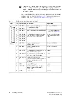
To reduce the standby current from 50mA to <3 mA without using the
ignition signal, connect pin 4 (AUX GPI3) and pin 15 (GND) of the
auxiliary connector.
Connecting the
Power Cable
Notice
Although it is possible to connect the radio in line with the
vehicle ignition, this is not recommended, as it may draw too much cur-
rent and damage the vehicle wiring and steering column or ignition
switch. This may also cause the supply voltage of the radio to drop
below the specified level.
Notice
Disconnecting the vehicle’s battery may cause problems with
some electronic equipment, such as vehicle alarms, engine management
systems, and in-vehicle entertainment systems. Check that the vehicle
owner has the necessary information to make all electronic equipment
function correctly after battery reconnection.
Notice
If the battery is not disconnected, exercise extreme caution
during the installation and install the fuses only when the installation is
ready to be checked. For more information, refer to
.
1.
Disconnect the vehicle’s battery unless specifically prohibited from
doing so by the customer, vehicle manufacturer, agent, or supplier.
Notice
Route the cable in a manner that minimizes coupling of elec-
tric vehicle systems such as alternators into the radio.
Notice
Protect the power cable from engine heat, sharp edges and
from being pinched or crushed.
2.
Run the power cable between the radio’s mounting position and the
power source and cut it to length, allowing approximately 8 inches
(200 mm) excess at the radio end.
3.
Plug the power cable into the power connector of the radio.
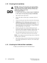
Warning
Danger of fire! The radio’s protection mechanisms
rely on the correct fuses on both the negative and positive power
supply leads being present. Failure to fit the correct fuses may
result in fire or damage to the radio.
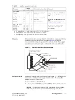
The correct fuse types are:
■
30-50W radios: 20A fuses (Tait IPN 265-00010-81)
■
25W radios: 10A fuses (Tait IPN 265-00010-80)
4.
Cut the negative and the positive wires where the in-line fuse holders
will be placed (as close to the power source as possible).
Notice
Do not install the fuses until the installation is ready to be
checked. For more information, refer to
“Checking the Installation” on
.
25W

