TM9300/TM9400 Installation Guide
Installing the Radio
37
© Tait Limited
December 2015
External Alert
Device
The radio allows for output to external alert devices using the digital GPIO
lines of the auxiliary connector and the internal options connector.
AUX GPIO4 can be fitted with a power MOSFET (Q10N) to directly
connect external alert devices (e.g. flashing light, buzzer, horn relay) to the
radio. Also, resistor R75N must be removed.
Notice
While the MOSFET is rated at 12 A (with heat sink), the max-
imum allowable current of the connector and radio’s earthing system is
2 A. Therefore, a horn must not be connected directly to the radio.
A horn relay must be used.
The selected output line must be programmed to ‘External Alert 1 or 2’,
active to ‘Low’, and signal state to ‘Momentary’.
■
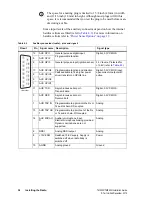
Connect the external alert device to the pin of the output line (pin 10 for
AUX GPIO4) and pin 8 (+13V8 SW) of the auxiliary connector (or a
different positive battery connection).
This means that the negative side of the alert device must be connected to
AUX GPIO4 and the positive side to pin 8 (+13V8 SW). The external alert
device must be capable of accepting a voltage of between 10V and 18V.
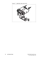
4.10 Installing the Radio
1.
Connect the antenna cable, power cable, and (if applicable) the
auxiliary cable to the rear of the radio.
2.
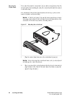
Position the radio in the U-cradle so that the holes in the U-cradle
line up with the holes in the radio chassis.
3.
Screw the radio into position using the four thumb screws provided,
but without fully tightening the screws.
4.
Adjust the position of the radio in the U-cradle for the best viewing
angle, then tighten the thumb screws.

