TM9300/TM9400 Installation Guide
Installing the Radio
33
© Tait Limited
December 2015
5.
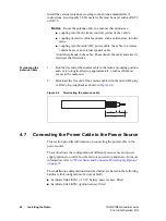
Insert each end of the negative wire into each of the fuse
crimp-terminals and crimp them to force the metal contacts onto
the wires.
6.
Push the two crimp-terminals into the clear plastic fuse cover. Close
the cover while the next steps are completed.
7.
Repeat steps 5 and 6 for the positive wire.
8.
Connect the negative wire to the battery ground terminal.
9.
Connect the positive wire to the battery positive terminal.
Notice
Do not install the fuses until the installation is ready to be
checked. For more information, refer to
“Checking the Installation” on
4.8
Connecting an External Speaker
An external speaker is connected to the speaker pins of the radio’s power
connector and operates in addition to the radio’s existing internal speaker.
For information about Tait external speakers refer to
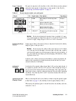
If a different speaker is used, receptacles for the speaker pins of the power
connector are provided with the radio’s installation kit.
■
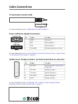
Connect the speaker to pins 2 (SPK–) and 3 (SPK+) of the power
connector described
For more information, refer to the installation instructions provided with
the speaker.
4.9
Connecting to the Auxiliary Connector
(Ignition Signal, Emergency Switch,
External Alert Devices)
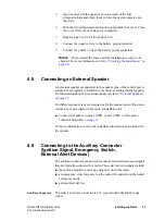
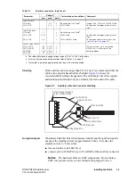
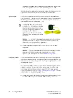
The auxiliary connector can be used to connect external devices and signals
that are typically connected to a radio. These devices and signals include:
■
the ignition signal to power up and power down the radio
■
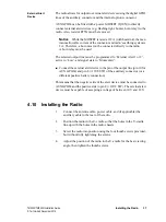
an emergency switch to power up the radio (if required) and then enter
emergency mode
■
external alert devices
Auxiliary Connector
The radio’s auxiliary connector is a 15-way standard-density D-range
socket.

