


6
TMAA04-06 Cross-band Linking, GPS and External Interface Cable
© Tait International Limited February 2021
Interface Specification
The following tables summarise the signals used for all connectors on the cable, and shows
the interfaces between the cable and the radios.
More Information
Please contact your nearest Tait provider for more information about this product.
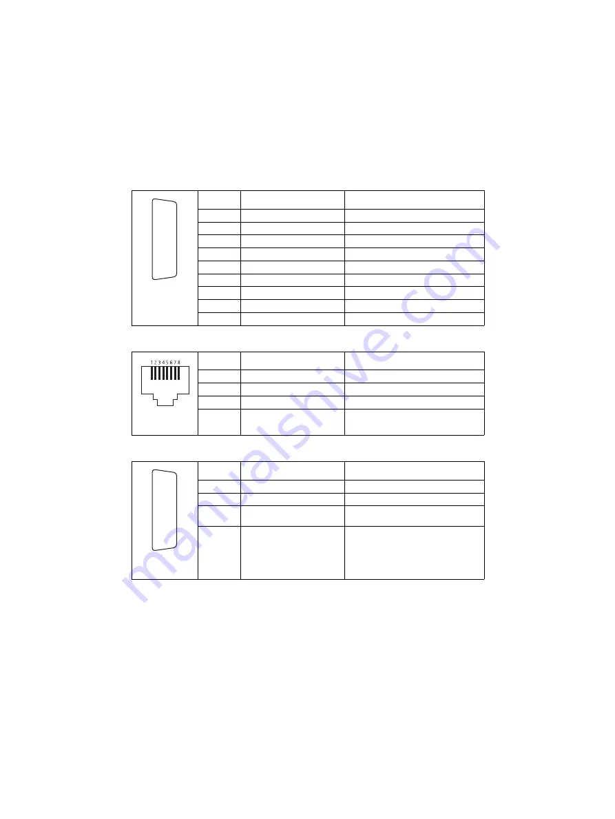
Auxiliary connectors—pins and signals
Pin Signal
name
Description
2
AUX_GPIO5
busy (output)
3
RXD
receive data
4
AUX_GPI3
ignition sense
7
AUD_TAP_IN
audio tap input
8
+13V8
power supply to GPS device
9
AUX_GPIO6
external alert
12
AUX_GPI1
PTT (input)
13
AUD_TAP_OUT
audio tap output
15
AGND
ground
GPS socket—pins and signals
Pin Signal
name
Description
1
+13V8
power supply from radio
2
GND
ground
3
GND
ground
5
GPS_TXD
transmit data
External interface connector—pins and signals
Pin Signal
name
Description
4
AUX_GPI3
ignition sense
9
AUX_GPIO6
external alert (radio closest to connector)
10
AUX_GPIO6
external alert (radio furthest from
connector)
15
GND
ground
rear view
J
B
C
D
E
F
G
H
I
1)
1!
1@
1#
1$
1%
front view
rear view
J
B
C
D
E
F
G
H
I
1)
1!
1@
1#
1$
1%


