background image

Midian Encryption Programming and Service Manual

PCB Information

63

© Tait Electronics Limited June 2006

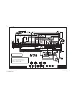
Circuit Diagram - page 1 of 1

SK102

FUNCTIONS

FOR GPIO6

AND GPIO7

IOP_GPIO6

CS4 /

WAKEUP /

INDICATOR

FROM MODULE

IOP_GPIO7

CS8 /

WAKEUP /

INDICATOR

FROM MODULE

LK8 3WAY LINK

1-2

FOR IND

TO GPIO6,

2-3

FOR IND

TO GPIO8

LK9 3WAY LINK

1-2

FOR GPIO7

TO CS8 (NORMAL)

LK10

3WAY LINK

1-2

FOR GPIO6

TO CS4 (NORMAL)

LK1 1-2

FOR AUDIO

GATE FROM RSSI

SIGNAL,

2-3

FOR EXT.

GATE

ENCRYPTION

MODULE

EXTERNAL

CONNECTOR

LINK

TABLE

TO RADIO

LK6 FOR EXTERNAL

INDICATOR

OF ENCRYPTION

LK3 AND LK4 FIT

FOR DIRECT

PGM TO TRANSCRYPT 400

SERIES

LK7 3WAY LINK

1-2

FOR GPIO7

TO RX (WAKE-UP

OPTION

FOR TELSEY)

LK5 ALERT TONES LINK

FOR GO AHEAD,

BEEP (NOT

PREESNTLY

USED)

LK2 EXTERNAL

PTT LINK

ALLOWS TM TO BE USED AS OTAR (NOTE

R19 MUST BE REMOVED)

Thu

Jul

28 16:45:00

2005

P3MM5_650C

MOUNTING

HOLE

HOLE

MOUNTING

P3MM5_650C

HOLE

MOUNTING

P3MM5_650C

TS914

MOUNTING

P3MM3_760C

100NF

100NF

+5V

LM397

DNI

MOUNTING

P3MM3_760C

MOUNTING

DNI

74V1G04

100NF

4053

DNI

100NF

10UF

LINK

IOP_GPI06

IOP_GPIO4

TS914

P3MM3_760C

HUGH

1

1

228_24341

CR-1

:

@\228_24341_LIB\.\228_24341\(SCH_1):PAGE1

VOUT

GND

VIN

R2OUT

GND

VCC

C1+

C2+

V+

C1-

C2-

R2IN

R1OUT

R1IN

T1OUT

T1IN

T2OUT

T2IN

V-

VCC

RST

GND

V+

V-

HOLE

HOLE

HOLE

HOLE

HOLE

HOLE

V+

V-

Y0

Y1

S

Z

V+

VEE

V-

EN

Y0

Y1

S

Z

+

V+

V-

+

+

+

Y0

Y1 S

Z

GND

I2

I1

O2

O1

O2

I2

O1

I1

GND

+

+

+

228-24341-02

A

XA2434-01

?

Hugh

Mathieson

+5V

+13V8_FUSED

100NF

100NF

10UF

LINK

5.6K

100NF

LINK

0

LINK

LINK

31/05/05

ADAM.D

?

M.HALL

MODIFICATIONS

21/02/05

01A

ADAM.D

?

HUGH

M.HALL

MOUNTING

TS914

TS914

TS914

47K

ADM202E

4053

1NF

100K

4053

VREF

+5V

100K

DNI

LINK

DNI

AUX_MIC_IN

1NF

AUD_TAP_OUT

RX_AUD

RX_MUTE

39K

LM397

100K

BAT165

I/OPAD

+5V

PTT_IN

PTT_OUT

BAT54S

VREF

TRK

AL

SC-RX

RX-SC

EMIF01

AUD_TAP_IN

+5V

+5V

+5V

P3MM3_760C

MOUNTING

DNI

DNI

DNI

MOUNTING

P3MM3_760C

DNI

1NF

1NF

TM8K ENCRYPT OPT BRD

STEVE C

M.HALL

HUGH

?

SK18MM

DGND

IOP_TXD

CS8

TX-SC

CS1

IND

CS2

D-RA

DNI

2.21M

+5V

15-9-04

SK15DR

CS8

+5V

AUX_MIC_IN

RSSI

LINK

CS2

IOP_GPIO2

00A

FIRST

PROTOTYPE

78M05

5V

IOP_GPI07

LINK

RSSI

IOP_GPIO1

IOP_RXD

DNI

SK20FL

IOP_GPIO3

IOP_GPIO5

CS4

P3MM3_760C

EMIF01

220K

220K

220K

220K

220K

4.7K

0

0

0

0

0

0

0

0

0

+5V

100NF

100NF

100NF

100NF

10K

CS1

RX_AUD

RX_BEEP_IN

DS1810

GND

CS4

CS2

IOP_RXD
IOP_TXD

100NF

100NF

+5V

LINK

+5V

100NF

+5V
RS
PTT

1NF

1NF

1NF

100NF

100NF

I/OPAD

LINK

100NF

8.2K

100K

0

100NF

DNI

0

I/OPAD

DNI

100NF

100NF

4053

10K

22K

VREF

VREF

100K

100NF

100K

1UF

22K

0

100NF

DNI

10K

SC-TX

GND

CS4

EMG

MD

RX

D-SC

+5V

I/OPAD

VREF

BC847BW

BC847BW

BC847BW

BC847BW

BC847BW

CS1

IND

+5V

D-RA

D-SC

1NF

100NF

100NF

300MA

13V8

+5V

AGND

CS8

MODE_ON/OFF

+13V8_FUSED

47K

22K

220K

10K

74V1G04

MINOR CHANGES

02A

SK102

1
2
3
4
5
6
7
8
9
10
11
12
13
14
15
16
17
18

C24

LK3

LK4

FL2

2

1

3

5

4

FL3

2

1
3

5
4

J3

LK6

J4

R29

R28

LK5

R23

D2

LK1

1

2 3

C20

C34

C33

C19

C1

C23

U2

1

4

3

C12

R19

R13

R18

D1

R17

R12

J1

C18

C11

R14

R15

R16

R27

R26

R25

R24

F1

J2

U1

3

1

2

U3

1

3
4

5

15

13

12

8

9

11

14

10

7

2

6

16

FL1

6

3

LVI

3

1

2

C14

C15

C16

C17

C36

C35

U2

2

5

C2

R55

SK1

1
2
3
4
5
6
7
8
9

10
11
12
13
14
15

16

17

MT4

1

MT3

1

MT2

1

MT1

1

J5

1
2
3
4
5
6
7
8
9

10
11
12
13
14
15
16
17
18
19
20

21

22

C25

C26

C27

C28

C13

C37

FL4

7

2

R33

R32

LK2

LK8

1 2

3

LK7

1

2

3

LK9

1

2 3

LK10

1

2

3

FL1

8

1

FL4

8

1

FL4

6

3

FL1

5

4

FL1

7

2

FL4

5

4

MT5

1
C29

C30

MT6

1

U5

2

4

U5

3

5

U6

10

2

1

15

U6

6

8

16

7

R20

R56

R57

R58

R60

R59

C49

C6

C5

U6

11

12

13

14

R53

C7

U7

6

7

5

U7

11

4

U7

2

1

3

R54

R50

C45

R49

U7

9

8

10

R47

R48

R46

U7

13

14

12

R44

R43

Q1

R34

R35

Q2

R36

R37

R38

Q4

R39

Q5

R11

C40

C46

C50

C48

U6

9

5

3

4

C43

C44

C39

C47

Q3

R40

R21

MT9

1

MT7

1

MT8

1

VIN

GND

VOUT

V-

T2IN

T2OUT

T1IN

T1OUT

R1IN

R1OUT

R2IN

C2-

C1-

V+

C2+

C1+

VCC

GND

R2OUT

GND

RST

VCC

V-

V+

HOLE

HOLE

HOLE

HOLE

HOLE

HOLE

V-

V+

Z

S Y1

Y0

EN

V-

VEE

V+

Z

S

Y1 
Y0

+

V-

V+

+

+

+

Z

S

Y1

Y0

O1

O2

I1

I2

GND

HOLE

HOLE

HOLE

GND

I1

O1

I2

O2

+

+

+

ENGINEER:

FILE

DATE:

VARIANT

NUMBER:

14

7

9

APVD

REV/ISS

4

13

14

K

12

J

H

G

F

11

10

8

E

D

C

B

A

12

11

10

8

4

3

K

1

2

G

F

J

H

6

7

5

DATE

D.O.

C

B

E

D

DRAWN

CHKD

3

AMENDMENTS

1

A

2

5

9

6

OF

SHEET

NUMBER:

13

FILE

NAME:

ISSUE:

IPN:

TAIT

ELECTRONICS

A1

Summary of Contents for TOP

Page 1: ...Tait Custom Solution Midian Encryption for Tait TOP and TM8000 Radios Operation and Service Manual MAS 02434 MD 02 June 2006...

Page 2: ...e Head Office Tait Electronics Ltd P O Box 1645 Christchurch New Zealand For the address and telephone number of regional offices refer to the TaitWorld website Website http www taitworld com Technica...

Page 3: ...nual or both without prior notice Copyright All information contained in this manual is the property of Tait Electronics Ltd All rights are reserved This manual may not in whole or in part be copied p...

Page 4: ...not included in manuals and to offer solutions for any problems that arise Document Conventions Within this manual four types of alerts may be given to the reader The following illustrate each type o...

Page 5: ...yption Module Settings 20 2 6 Testing the Midian Encryption Module 25 2 7 Programming Cable Specifications 26 3 Tait Orca Portable TOP Encryption 29 3 1 User Interface 29 3 2 Circuit Operation 29 3 3...

Page 6: ...6 Contents Midian Encryption Programming and Service Manual Tait Electronics Limited June 2006...

Page 7: ...proval to operate the equipment Equipment Safety ESD Precautions Important This equipment contains devices which are susceptible to damage from static charges You must handle these devices carefully a...

Page 8: ...due to variations in manufacturing techniques Pozidriv Recess Head Screws Pozidriv recess head screws are used in Tait equipment in a few special applications It is important that you use the correct...

Page 9: ...his manual to list every tool that a service technician should carry However the tools specifically required for servicing encrypted TOP and TM8000 radios are listed below Fine tipped 1 2mm temperatur...

Page 10: ...s The two satisfactory methods of removing components from plated through hole PTH PCBs are detailed below Desoldering Iron Method This method requires the use of a desoldering station 1 Place the tip...

Page 11: ...removed before attempting to lift the capacitor Encryption Modules Important The encryption module can control the radio PTT and while programming may cause the radio to transmit Always provide protec...

Page 12: ...12 Safety and Servicing Information Midian Encryption Programming and Service Manual June 2006 Tait Electronics Limited...

Page 13: ...ected the radio sends and receives encrypted calls to and from other radios with compatible encryption module and settings However even when encryption is not selected an encryption enabled radio will...

Page 14: ...yption modules from different manufacturers are not compatible features available in a Tait encryption enabled radio are not necessarily the full list of features specified by the module manufacturer...

Page 15: ...5 Tait Encryption Products At the time of printing the following encryption products were available for ordering However further encryption products are regularly being added for further information...

Page 16: ...ription Comments TOPA EA 011 Charge Program Test Ecrypt Kit Factory fitting and programming of encryption module IPN Description Comments TOPA EA 003 KIT Midian KL3 prog cables Tait Orca and TM8000 En...

Page 17: ...itting a module into a TM8000 radio as these snap offs include screw holes necessary to fit the module The snap offs are removed for TOP applica tions 2 2 Radio Hardware Compatibility TOP Radios The T...

Page 18: ...mming a Midian module it is strongly rec ommended that you use the manufacturer s default secu rity codes See the Midian programming manual for more information on standard codes and instructions for...

Page 19: ...03026 0X see Cable Specifications on page 25 Note The Midian KL3 programmer includes a dedicated programming cable However as this cable requires the radios to be opened its use is not recommended or...

Page 20: ...oftware commands and register values Before programming the Midian encryption module it is important to understand the meaning of various identifiers in the programmer manual Some of these are outline...

Page 21: ...une 2006 Tait Electronics Limited Encode Decode Tab Security Keys Tab Important The settings on this page cannot be read back all security codes will read 00000000 It is strongly recommended that all...

Page 22: ...22 Midian Encryption Midian Encryption Programming and Service Manual June 2006 Tait Electronics Limited Scrambler Tab Input Output Tab...

Page 23: ...d Tab Miscellaneous Tab VPU12 Tait Factory Default Settings The screen dump that follows illustrates the current VPU12 Tait module programming interface and factory default settings For information re...

Page 24: ...it audio are functioning using another TM8000 or TOP radio with the same encryption module programmed with the same codes on the same channel Confirm encryption is active where a hopping code module i...

Page 25: ...pin 2 Ground Black pad 2 GND pin 1 IPN Description Qty 205 00010 42 CBL oval 6wy std Telecom 1000mm 240 00020 08 PLG 6wy mdl ph oval cbl 1 303 20067 01 Lok Spring D Clip Release 1 308 01021 00 Hsng Mi...

Page 26: ...ing Cable can be used with any Midian encryption module It connects the radio via its programming port to the Midian KL3 Programmer Parts List 6 11 15 10 5 1 Pin 15 Pin 6 Pin 7 White Blue Red 3mm stri...

Page 27: ...ere the radio has both a display and a keypad it also provides encryption state by text on the radio display user control of up to 16 encryption codes by keypad continuous display of the currently sel...

Page 28: ...on the flex The external PTT and internal PTT are combined within the radio software to provide the PTT for the module The module IND status output is fed to the SENSE 1 input to the radio micro This...

Page 29: ...Reset I P RS 2 Active low Resets whenever supply lower than 4 75V Tx pressel I P PTT 3 Active low CMOS Busy I P RX 4 Active low CMOS Mode I P MO 5 Active low Momentary or level sensitive Data to Scra...

Page 30: ...details then click on Tait only 2 Select Portable Radios then Encryption 3 Select the correct Programming Software As a guide Select 2259 for 501X and 502X radios 2275 for 503X and 504X trunked radios...

Page 31: ...ion form set the Maximum Number of Encryp tion Codes to a number between 1 and 16 2 In the Key Settings form choose a function key to assign to Encryption On Off and another for Encryption Code Select...

Page 32: ...ailure to decode some encrypted calls after a period of inactivity If radios have no display ensure no other function eg incoming selcall or repeater talkaround is programmed to utilise the orange LED...

Page 33: ...ion User Interface features status indicators encryption settings etc See the TOP Operating Instructions that follow 3 6 TOP Operating Instructions These operating instructions apply to encryption ena...

Page 34: ...plugged Module faulty Replug connectors checking that the flex is square to connector Replace module Radio set to one code can hear another radio no matter what code it is set to Module may have same...

Page 35: ...bling the radio as failure to disassemble it correctly may damage the seal and shield resulting in permanent damage Disassemble according to the standard pro cedures documented in the TOP Service Manu...

Page 36: ...iver to undo screw and remove PCB from chassis 2 Remove component C572 using hot air gun and tweezers 3 Remove component Q532 using hot air gun and tweezers 4 Remove component R356 using hot air gun a...

Page 37: ...can with large hole cut as shown 2 If there is no large hole in the can cut carefully with sidecutters where shown and turn the edges in 3 Remove capacitor C567 using a hot air gun and tweezers 4 Remo...

Page 38: ...ss locking tabs closed 3 Solder two flex pads to the position vacated by C572 4 Ensure flex fits exactly to corner of can with the edge clear of the PA can tag 5 Solder flex to cans holding soldering...

Page 39: ...ase then holding flex in place with tweezers solder flex pads to the pads vacated by C567 3 Solder flex to can holding soldering iron to each point for at least three seconds to ensure permanent join...

Page 40: ...PCB back into chassis 1 Slide PCB back into chassis carefully aligning the chassis Auxiliary Connector Flex into the PCB top side 2 Replace the screw through the can where shown 3 Replace the washers...

Page 41: ...Remove R5 and R6 on flex 2 Fit flexiloom firmly into module s flex edge connector 3 With main RF shield beside PCB as shown fit flex into RF shield flex edge connector Note There is no flex edge conn...

Page 42: ...3MM FLEXI BRD 1MM SPAN R2 036 14470 10 RES 4K7 1 R4 036 15470 10 RES 47K 1 R5 036 15100 10 RES 10K 1 R6 036 15100 10 RES 10K 1 R7 036 10000 00 RES ZERO OHM 5 R8 036 15100 10 RES 10K 1 R9 036 15100 10...

Page 43: ...le TOP Encryption 43 June 2006 Tait Electronics Limited PCB Layout top side only C1 C2 C3 D1 IC1 LINK2 LINK3 LINK4 LINK5 LINK7 P1 P11 P12 P13 P18 P19 P2 P20 P21 P22 P24 P25 P27 P28 P4 P5 P6 P7 P8 PL1...

Page 44: ...owever the following information may be helpful regarding link settings Link Purpose Setting 1 Not assigned 2 Alarm output Future development 3 Indicator output to LED Not normally used 4 Rx Squelch F...

Page 45: ...Midian Encryption Programming and Service Manual PCB Information 45 Tait Electronics Limited June 2006 Circuit Diagram page 1 of 1...

Page 46: ...46 PCB Information Midian Encryption Programming and Service Manual Tait Electronics Limited June 2006...

Page 47: ...y D range external connector to the encryption module mounted on the options board a 20 way connector via the flexible loom IPN 219 02129 00 supplied All encryption enabled TM8000 series radios are fa...

Page 48: ...iagram that follows illustrates the operation of the XA2324 01 circuitry GPIO port GPIO1 sends PTT to the module and GPIO2 detects PTT from the module As the module s PTT line is common D2 and IC U6 a...

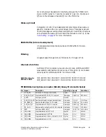
Page 49: ...are available for alternate functions via Links 7 through 10 Note links are normally set for GPIO6 and GPIO7 to CS4 and CS8 SK102 Functions for GPIO6 and GPIO7 IOP_GPIO6 CS4 WAKEUP INDICATOR FROM MOD...

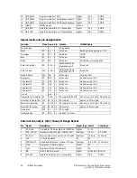
Page 50: ...select 8 I P CS8 10 Active Low Module pull up to 5V Code select 4 I P CS4 11 Active Low Module pull up to 5V Code select 2 I P CS2 12 Active Low Module pull up to 5V Code select 1 I P CS1 13 Active L...

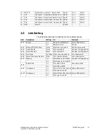
Page 51: ...efault 2 3 External Rx Mute SK1 pin1 Link 2 External PTT OTAR base Fitted Fit link and remove R19 R19 must be removed Link 3 Direct PGM IN Fitted Fit for direct PGM Not used in this application Link 4...

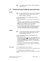
Page 52: ...Electronics Limited 4 4 Programming the TM8000 radio Note In addition to standard customer and application specific programming settings all TM8000 radios require the following specific I O settings...

Page 53: ...lashing code If no further buttons are pressed display reverts to channel display and enters displayed flashing code after approximately eight seconds TM8200 Note Encryption changes to standard TM8000...

Page 54: ...ear another radio no matter what code it is set to Module may have same code strings set in all code registers On TOP radio flex IC1 may not be working or not getting address information from micro Re...

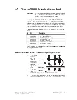
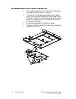
Page 55: ...Encryption Options Board Use the diagrams and the instructions that follow to assemble or disassemble the encrypted TM8000 radio Fit Midian Encryption Module to TM8000 Encryption Options Board 1 Fit t...

Page 56: ...shown 2 Turn Encryption Options Board over and place board so that the external D Range protrudes through the rear aperture of the chassis Then using six Taptite screws fit Encryption Options Board to...

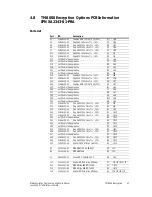
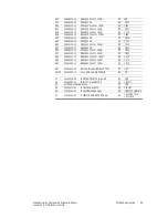
Page 57: ...tion F1 1A6 C27 not fitted in this application B6 1A7 C28 not fitted in this application G5 1A8 C29 not fitted in this application B10 1A8 C30 not fitted in this application G9 1A9 C33 018 16100 00 Ca...

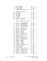
Page 58: ...10 RES 0603 2M21 1 1 10W C3 1J2 R13 038 14560 00 RES 0603 5k6 5 1 10W C2 1J3 R14 038 10000 00 RES 0603 0R C3 1H3 R15 038 10000 00 RES 0603 0R B2 1J3 R16 038 10000 00 RES 0603 0R B3 1J4 R17 038 15390...

Page 59: ...R55 038 10000 00 RES 0603 0R G4 1B12 R56 038 15470 10 RES 0603 47k 1 1 10W D4 1B12 R57 038 15100 10 RES 0603 10k 1 1 10W D4 1B13 R58 038 16100 10 RES 0603 100k 1 1 10W E4 1C13 R59 038 15220 10 RES 06...

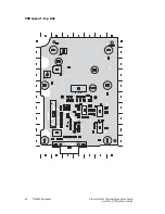
Page 60: ...60 TM8000 Encryption Midian Encryption Programming and Service Manual June 2006 Tait Electronics Limited PCB Layout top side...

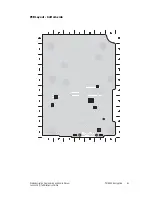
Page 61: ...Midian Encryption Programming and Service Manual TM8000 Encryption 61 June 2006 Tait Electronics Limited PCB Layout bottom side...

Page 62: ...62 TM8000 Encryption Midian Encryption Programming and Service Manual June 2006 Tait Electronics Limited...

Page 63: ...V 15 9 04 SK15DR CS8 5V AUX_MIC_IN RSSI LINK CS2 IOP_GPIO2 00A FIRST PROTOTYPE 78M05 5V IOP_GPI07 LINK RSSI IOP_GPIO1 IOP_RXD DNI SK20FL IOP_GPIO3 IOP_GPIO5 CS4 P3MM3_760C EMIF01 220K 220K 220K 220K 2...

Page 64: ...64 PCB Information Midian Encryption Programming and Service Manual Tait Electronics Limited June 2006...

Reviews: