9
3.1.1 RETRACTI
ON
OF
THE
DI
SCHARGE
CONVEYOR
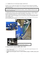
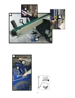
Discharge conveyor is usually telescopically retracted in the machine transport position. By activating the
machine, telescopic cylinder of the discharge conveyor automatically activates and fully extends the machine,
so the belt is tensioned.
3.2 TRACTOR PTO SHAFT DRIVE (RCA 320-2):
•
P.T.O. shaft (grooved shaft 13/8!" Z6 – DIN 9611A) must comply with the required driving power of the
machine (technical data).
•
The tractor P.T.O. shaft must rotate in a clockwise direction.
•
Recommended rotating speed of the P.T.O. shaft: 420 RPM; maximum: 430 RPM,
minimum: 400
RPM
4
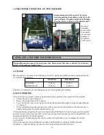
T
2
t
Ensure the clearance “t” between the nut
and the hand winch handle axis.
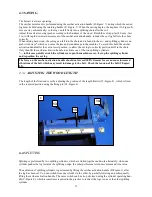
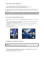
Before starting the machine, make sure to loosen the conveyor belt, by moving the Discharge Conveyor from
vertical to horizontal position using the hand winch (3-Figure:3). Otherwise damages to the belt can occur
during the extension procedure!
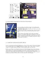
To optimally tension the belt, move the control handle of the lifting table (E-Figure: 1) to the lowering positi-
on, which increases the system pressure. To position the Discharge Conveyor into the working – extended
position, the discharge conveyor valve (T:Figure:1) must be closed – fully tightened.
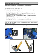
After you disconnect the machine drive, you can retract the discharge conveyor. Open the discharge conveyor
valve (T-Figure: 1) and leave the discharge conveyor to retract by its own weight. Therefore put the machine
in more upright position.
When the discharge conveyor is retracted, close the discharge conveyor valve (T-Figure: 4). The valve must
be also closed during the operation.


