background image

13

4.3 SAWING

The barsaw is always operating.
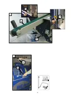
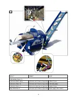
The sawbar movement is performed using the sawbar activation handle (H-Figure: 7), during which the sawed 
log must be held using the retaining handle (P- Figure: 7). When the sawing begins, the trapdoor (13-Figure:8)
moves away automatically, so the log can fall freely into a splitting chute after the cut.
Adjust the sawbar moving speed according to the hardness of the wood. Finish the cut (app. last 20 mm - last 
1 in ) with rapid downward movement of the sawbar activation handle, to make the cut log fall into the chute 
correctly.
When cutting hard wood, the cut log can fall into the chute and rebound in the air - and splitting cylinder can 
grab it sideways*, which can cause the jam and even damage to the machine. To avoid this, hold the sawbar 
activation handle after the cut in lower position, to allow the cut log to correctly position itself in the chute. 
Only then lift the sawbar activation handle to activate one of the two splitting cylinders. 
*

…  in this case quickly switch the cylinders or open the machine cover, to stop the splitting cylinder 

and reposition the cut log. 

4.3.1

ADJUSTING THE WOOD LENGTH 

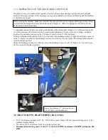
The length of the firewood is set by adjusting the position of the length limiter (15-Figure:8) , which is fixed 
in the required position using the fixing pin (14-Figure:8).

4.4

SPLITTING

Splitting is preformed by two splitting cylinders, which are linked together and work alternately: when one 
cylinder pushes the log towards the splitting wedge, the other performs a return movement and vice versa.

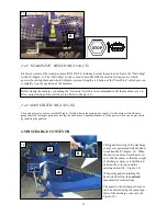
The activation of splitting cylinders is performed by lifting the sawbar activation handle (H-Figure:1), after 
the log has been cut. You can switch from one cylinder to the other, by partially lowering and subsequently 
lifting the sawbar activation handle. The same switch can be also performed using the cylinder operating han-
dle (C-Figure:9), which is sometimes required in the practice to redirect the logs to one or the other splitting 
cylinder.

The force on the sawbar activation handle should not exceed 100N. Greater force can cause increased 
vibrations of the belt, which may result in damage to the belt.  Check the tension of the belt (Chapter: 
5.9).

8

15

14

13

Summary of Contents for RCA 320-2

Page 1: ...2 0 F ax 3 8 6 0 35 7 9 10 1 6 E m ail ex port tajfun si h ttp www tajfun c om 05 2006 GB R RC CA A 3 32 20 0 2 2 Please carefully read the operating instructions before using the machine O OP PE ER RA AT TI IN NG G I IN NS ST TR RU UC CT TI IO ON NS S F I REW OOD P ROCES S OR 082 00 000 R RC CA A 3 32 20 0 2 2 E E 083 00 000 ...

Page 2: ...HEWOOD L ENGT H 13 4 4 SPLITTING 13 4 4 1 ADJ US T I NG T HEHEI GHTOFT HES PL I T T I NG WEDGE 14 4 4 2 MACHI NECOVERWI T H S AFET YS WI T CH 14 4 5 DISCHARGE CONVEYOR 15 Chapter 5 M AI NTENANCE AND REPAI R 16 5 1 CHAIN REPLACEMENT 16 5 2 CHAIN TENSIONING 17 5 3 SPLITTING WEDGE REPLACEMENT 17 5 4 HYDRAULIC SYSTEM OILCHANGE 17 5 5 OILFILTER MAINTENANCE 18 5 6 LUBRICATION OF THE ANGLE REDUCTION GEAR...

Page 3: ... ADDRESS Ta j f u nPl a n i n a d o o Pl a n i n a41a 3225 Pl a n i n ap r i Se v n i c i Sl o v e n i j a Te l 38 6 0 3 746 44 20 Fa x 38 6 0 3 579 1 0 16 E ma i l e x p o r t t a j f u n s i h t t p www t a j f u n c o m A Feed Conveyor H Saw b ar activation Handle B M achine Cover w ith Safety Sw itch J Dis charge Conveyor C Sp litting Cylinders Control Handle K Dis charge Conveyor s s p eed Re...

Page 4: ...egrated in machine control panel Chain 3 8 Oregon MULTI CUT 32 Number of driving teeth 60 b 0 058 1 5 mm Discharge Conveyor s speed regulator integrated in Dis charge Conveyor Manual Winch Operating Ins tructions Sawbar Oregon 168SLHD009 or compatible Electric Motor 11 kW RCA 320 2 E 1 4 OPTIONAL EQUIPMENT LOG LOADER DM 1501 Taj fun Oil Cooler ELECTRIC POWER UNIT EP 11 Taj fun 2 DM 1501 Chain lubr...

Page 5: ...5 EP 11 ELECTRIC POWER UNIT EP 11 Tajfun Motor Power 11 kW Weight 197 kg ...

Page 6: ...0 min 1 RPM Max imum p r es s ur e 250 b ar Oil Res er v oirVol ume 100 l 25 gal Chain Lub r ic ation Oil Res er v oirVol ume 8l 2 gal Op er ating Nois e Max RCA 320 2 92 d B A RCA 320 2 E 96 d B A Weight RCA 320 2 8 00 k g 17 64 l s RCA 320 2 E 900 k g 198 5 l s Conv ey orLength 4000 mm 13 Conv ey orBel t Wid th 430 mm 17 5 Max imum Sp eed 60 c m s 24 Weight 130 k g 28 6 l s Discharge Conveyor El...

Page 7: ... e Fo ry o u ro wns a f e t yu s eo n l yo r i g i n a l s p a r ep a r t sa n da c c e s s o r i e swh i c ha r ea p p r o v e db yt h ema n u f a c t u r e r Th ema c h i n emu s t b eg r o u n d e da c c o r d i n gt or e g u l a t i o n s RCA3 2 0 2E Da ma g e dp o we rc o r do rp l u gmu s t b er e p l a c e di mme d i a t e l y RCA3 2 0 2E 3 M ACHI NES ETUPAND OPERATI ON Mount the firewood p...

Page 8: ...HARGE CONVEYOR ASSEMBLY in case of sep arate d eliv ery Hydraulically driven discharge conveyor is also a component part of the firewood processor Place the discharge conveyor on the ground and move it closer to connecting spot Slide the discharge conveyor on the supporting forks and secure it with two screws 1 F igure 3 F asten the lifting package by fixing rope pulleys to their position 2 F igur...

Page 9: ...ing the machine make sure to loosen the conveyor belt by moving the Discharge Conveyor from vertical to horizontal position using the hand winch 3 Figure 3 Otherwise damages to the belt can occur during the extension procedure To optimally tension the belt move the control handle of the lifting table E Figure 1 to the lowering positi on which increases the system pressure To position the Discharge...

Page 10: ...T O shaft 420 RPM using the manual throttle handle Lower the machine cover RCA 320 2 RCA 320 2 E Examine the machine and equipment for faults and check the chain lubrication Plug the machine to electric power source Turn on the Main Switch R Figure 1 Lift the machine cover B Figure 1 to activate the safety switch and allow easier starting of the electric motor Push the Start Stop switch green butt...

Page 11: ...e supporting leg 11 Figure 6 Set the supporting leg so that the upper rod on the conveyor belt in the middle of the feed conveyor is slightly elevated above the table already factory set Activate the feeding by pushing the sawbar activation handle H Figure 1 from the upper position neutral position forward away from yourself you can stop it at any time when the log reaches length limiter by return...

Page 12: ...12 7 H P 6 A 11 12 10 ...

Page 13: ... uickly switch the cylinders or open the machine cover to stop the splitting cylinder and reposition the cut log 4 3 1 ADJUSTING THE WOOD LENGTH The length of the firewood is set by adjusting the position of the length limiter 15 Figure 8 which is fixed in the required position using the fixing pin 14 Figure 8 4 4 SPLITTING Splitting is preformed by two splitting cylinders which are linked togethe...

Page 14: ...of overload 10 L 4 4 2MACHINE COVER WITH SAFETY SWITCH In case of eventual problems during the splitting phase or in case the log is wrongly positioned in the splitting chute the splitting process must be stopped immediately In this case it may be also necessary to switch the cylinders so the splitting cylinder which pushes towards the splitting wedge moves back 4 4 Machine cover B Figure 11 is li...

Page 15: ...CA 320 2 E includes besides the main switch also the Start Stop switch S Figure 1 The Start Stop switch is used to turn ON OFF the electric driving motor which powers the cutting chain and whole hydraulic system Using the red button of the Start Stop switch you can completely stop the operation of the machine Before staring the machine or pushing the start stop switch it is recommended to lift the...

Page 16: ...n tensioning screws 33 Figure 15 Unscrew both nuts 34 Figure 15 on the fixing plate 35 Figure 15 until you can move the sawbar away from the tensioner Remove the worn cutting chain and replace it with new well sharpened chain Make sure the cutting teeth are turned in the right direction the cutting edge on the top of the sawbar must face the machine controls Replace the cutting chain in a reverse ...

Page 17: ...and wood remains from the splitting wedge area splitting chute and under the mac hine Activate the splitting cylinders and open machine cover when the cylinders reach the middle position to make enough room for splitting wedge replacement Put the handle of the splitting wedge L Figure 16 in the right position to lower the splitting wedge completely Remove the splitting wedge from its mount and rep...

Page 18: ...ally damaged Bad filter permeability is shown on the filter gauge if the gauge indicator is in the red zone when oil is heated to operating temperature Change the oil filter 5 6LUBRICATION OF THE ANGLE MULTIPLICATION GEAR RCA 320 2 Oil quantity and grade 1 2 l 0 32 gallon SAE 75 Renolin CLP 100 DIN 51 517 13 Replace the oil when changing the reduction gear bearings 5 7CUTTING CHAIN LUBRICATION Nev...

Page 19: ...is overheating Not enough oil in the reservoir Check the oil level and add more if The machine is overloaded Remove the overloading causes Excessive power consumption during sawing The chain is dull Sharpen or replace the chain The chain is not properly tensioned Tension the chain The chain is covered with resin Clean the chain using the solvent i e Nit ro Solvent or replace the chain Louder opera...

Page 20: ...tting Replace the belt 5 10 4 3 check the cutting chain and use lower force on the operating handle Torn cutting chain drive belt The log too heavy or jammed Position or cut the log shorten the log Stuck wood is preventing the conveyor belt from moving Clean the conveyor belt area stop the machine during cleaning procedure 5 9 MAINTENANCE PLAN The machine must be turned off the P T O shaft must be...

Page 21: ...At least every 80 hours of operation Lithium Grease Lubrication Point d At least every 80 hours of operation Lubricating Spray Lubrication Point e At least every 8 hours of operation Lithium Grease Rope lubrication f At least every 80 hours of operation Grease apply with a brush ...

Page 22: ...22 Remove the belt 46 Figure 22 from the driven pulley 47 Figure 22 Remove the old belt and clean the area Install the new belt Position the belt onto the pulleys Tension the belt and reinstall removed elements lubrication pump 44 Figure 22 drive protection 41 Figure 22 housing cover 42 Figure 22 drive cover 43 Figure 22 After one hour test operation recheck the tension of the belt disconnect the ...

Page 23: ... using the notch on the tension indicator The notch must be aligned with the edge of the spring guide Set the tension of the belt as follows Loosen the safety nut 47 Figure 23 Screw or unscrew the spring guide as appropriate 48 Figure 23 and correctly align the notch Tighten the safety nut 47 Figure 23 23 48 47 ...

Page 24: ...ny modificati ons to the machine 5 12 SUPPLIES The machine incorporates following parts which have to be replaced by the customer as necessary These parts are not covered by the warranty period which is defined in the warranty statement Cutting chain Drive chainwheel Cutting chain guide sawbar Cutting chain drive belt Electric motor driven belt Cylinder wire rope Conveyor wire rope In feed conveyo...

Page 25: ... De c l arat i on ofConf ormi t y Manufacturer TAJFUN Planina proizvodnja strojev d o o Planina 41a 3225 Planina pri Sevnici d ecl areswi thful l res p o ns i b i l i tyth at h erei nafter menti o nedp ro d uct FI REW OOD PROCESSOR RCA 320 2 co v eredb yth i sd ecl arati o n co mp l i eswi thth e req ui rementso f EEC Mashinery Directive 98 37 EEC P l anina 0 6 1 2 2 0 0 5 I z to kŠ p an General M...

Page 26: ...i Sevnici declares with full responsibility that hereinafter mentioned product FIREWOOD PROCESSOR RCA 320 2 E covered by this declaration complies with the requirements of EEC Mashinery Directive 98 37 EEC Electromagnetic compatib ility regu lation EMC Of f icial Gazette ofRS No 61 00 Directive 89 336 EEC Ru les on electrical eq u ipment d esignedf or u se within certain voltage limits Of f icial ...

Page 27: ...27 ...

Reviews: