14
4.6. SETTING THE WINCH PULLING POWER
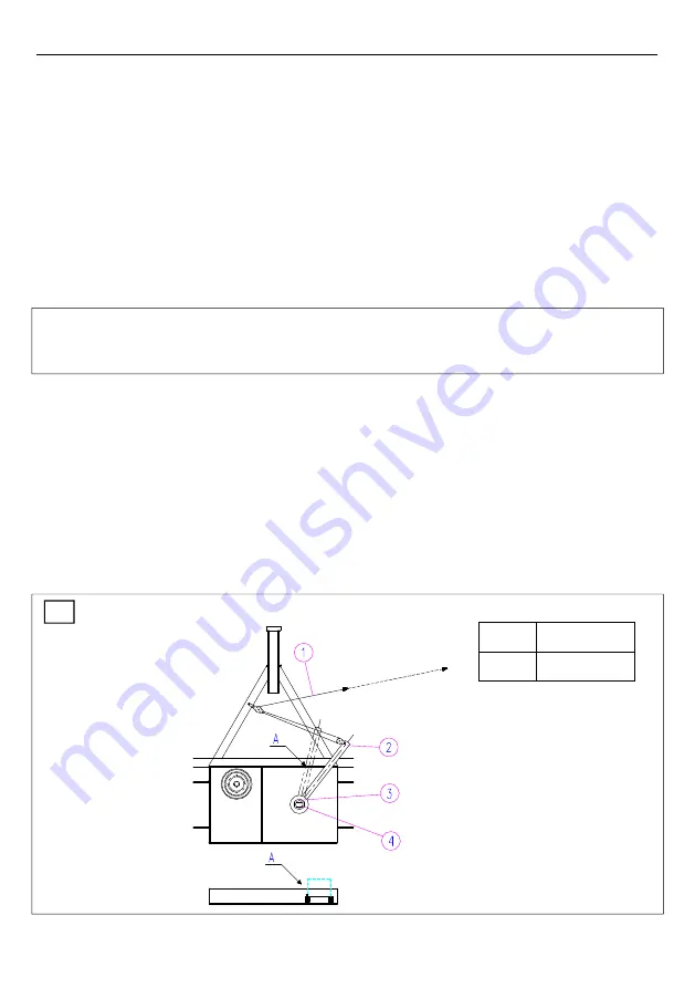
(Figure 8)
Each winch is factory set to its
maximum
pulling power which is also specified on the winch
type plate. Increasing of the pulling power over this value is
not allowed
. After the pulling
power of the winch decreases due to the wear of clutch linings, the clutch must be readjusted.
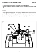
Pulling power setting procedure:
Disconnect the PTO shaft and shut down the tractor.
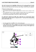
Use the spanner No 30 to release the safety plug
4
on the drum axis by turning it to the
left.
Use the spanner No 50 to turn the nut
3
M40 to the right so that you can pull the string
1
,
by using force “F” to move the clutch handle
2
to the end of the groove
A
.
Screw the safety plug
4
tightly to prevent the nut M40 from releasing.
It is important to tighten the nut M40 only so tight, that you can still pull the clutch
handle 2 to the end of the groove A using the force “F” and reach the nominal pulling
power (See Chapter: 4.2.)!
By proper adjustment of nut
M40
, set the nominal pulling power.
If the nut
M40
is set too tightly, you cannot move the handle
2
to the end of the groove and
pulling power decreases. If the nut
M40
is set too loose, it causes excessive deviation of
the drum, which can cause falling of the clutch plates off it’s pins. If this happens, the
whole drum must be dismantled.
»F«
35 A
250 N
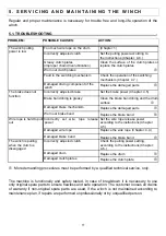
8


