INS
TALLA
TION
12
On-Demand Water Heater Installation Manual and Owner’s Guide
INSTALLATION
Installation environment
Warning! Do not store or use flammable
materials, vapors, or liquids in the same location
where this water heater is installed.
Before installing the water heater, ensure that it will be
located as described on p. 8 through 10. In addition to that,
the following factors shall be taken into account for the
installation location and method. Refer to each section in
the installation manual.
Atmosphere temperature
Install the water heater in a heated area where below
freezing temperature cannot occur. Units installed in areas
subject to below freezing temperature MUST follow the
steps outlined on p. 49. The pipe cover or recess box is
recommended when the water heater is installed outdoors
because it provides better protection from the elements.
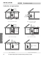
Combustion air supply
The water heater requires fresh combustion air should be
free of corrosive elements and flammable vapors. If it is
installed at the contaminated area or in a confined area,
direct venting installation is recommended. (Refer to pp. 17
to 25.)
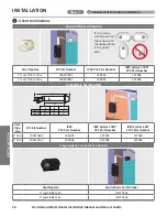
Proper ventilation
For proper operation the water heater must be vented in
accordance with the section “Venting of Equipment” of the
current edition of the National Fuel Gas Code: ANSI Z223.1/
NFPA 54 in the United States and/or Section 8 of the B149.1
Natural Gas and Propane Installation Code in Canada, as well
as applicable local building codes. (Refer to pp. 14 to 30.)
Proper mounting and clearance
The water heater shall be securely mounted on wall that
can support the weight of the water heater. A wall mounting
bracket is supplied with the water heater to securely mount
the water heater to wall studs. (Refer to p. 13.) The water
lines, gas line, condensate drain line, and pressure relief
valve discharge line shall be supported using field supplied
pipe hangers. The water heater shall not bear the weight of
these lines. The water heater requires proper installation
clearance for operation and service as described in the right.
Condensate Drain line
The condensate produced is acidic. Drain the condensate in
accordance with all local codes and common safety practic-
es. (Refer to p. 44.)
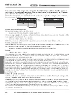
Unit clearances
Warning! Maintain all clearances around the
water heater. Failure to do so could create a
fire hazard, potentially leading to death, serious
injury, and/or property damage.
Indoor
T
op:
12 in (305 mm)
Front
:
4 in (102 mm)*
Back
:
0.5 in (13 mm)
Side
3 in (76 mm)
Bottom
:
18 in (458 mm)
*24 inches (610 mm) recommended for maintenance.
Outdoor
T
op:
36 in (914 mm)
Front
:
24 in (610 mm)
Back
:
0.5 in (13 mm)
Side
3 in (76 mm)
Bottom
:
18 in (458 mm)
Step 3:
Installation environments and unit clearances
Step 3:
Installation environment and unit clearances
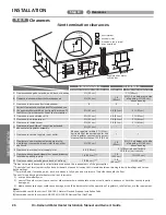
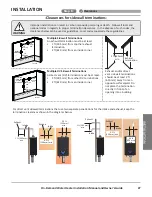
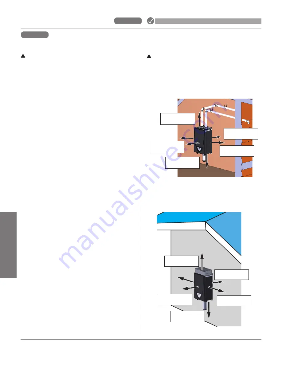
Summary of Contents for 160X3P
Page 84: ...7J8071 1 2000570774 REV B...


