INS
TALLA
TION
34
On-Demand Water Heater Installation Manual and Owner’s Guide
INSTALLATION
Step 11:
LP gas conversion
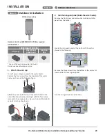
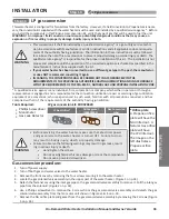
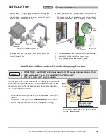
8. Install the LP orifice plate and gasket on the gas solenoid valve assembly as
shown in Figure 5. Secure the orifice plate by hand tightening the 2 screws.
Ensure that the orifice, gasket and two screws are in good condition and not
compromised in any way. If damage is found replace them with new ones. (Part
number: 100320420) Improper installation of the orifice and gasket may cause
a gas leak.
9. After checking an oval ring is in a good position in the ventury, install the gas
solenoid valve assembly to the venturi as shown in Figure 4. Use a Phillips
screwdriver to hand tighten the 3 screws to secure the assembly (Figure 3).
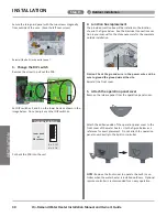
10. Inspect the o-ring on the gas supply tube. If there is any damage, replace it with
part number 100320422. Insert the tube into the gas valve assembly. Secure
the tube to the assembly by inserting the fastener over the gas supply tube.
11. Locate the PCB in the right side of the bottom of the water heater case and
remove the screw indicating in Figure 1.
12. Pull out the PCB and set the DIP switches on the PCB to the correct position for
propane by setting DIP switch #1 of the lower bank to the ON position and DIP switch #2 to the OFF position as
shown in Figures 6.
13. Put back the PCB into the case and reattach the removed
screw. (Figure 1)
14. Verify that the gas supply pressure is within an
acceptable range. (Refer to “Gas Supply and Gas Pipe
Sizing for Propane” on p.31.)
15. After the water heater has been installed and the gas
line pressure test has been completed, perform the
following steps:
a. Turn on the water supply.
b. Turn on the gas supply.
c. Turn on electrical power.
16. Check for gas leaks around the water heater as follows:
a. Turn on a nearby hot water faucet.
b. Wait until a consistent flame is seen through the sight glass.
c. Check for gas leaks by running a gas leak detector along the gas
passage. If you find a leak, stop operating the water heater and
turn the gas supply off.
17. Turn off the hot water faucet.
18. After the water heater has completed its post-purge process, turn off the gas supply and turn off power to the
water heater.
19. Verify the static and dynamic gas pressures for the water heater. Refer to the step no. 3 to 16 of “Measuring
inlet gas pressure” in this manual.
20. Check the combustion status as described on the following page.
21. Put back the PCB into the case and reattach the removed screw. (Figure 1)
22. Reinstall the front cover with the removed four screws.
23. Fill out all items on the gas conversion sticker with a permanent marker. Affix the label on the heater as shown
in Figure 7.
24. Restart the water heater according to the Installation Manual and Owner’s Guide.
Verify proper
operation before
returning the
water heater to
service.
Figure 2
Figure 3
Figure 4
Figure 1
Figure 7
Gas
conversion
label
1
2
3
4
5
6
7
8
ON
1
2
3
4
5
6
7
8
ON
Natural
LP
Figure 6
NA
Figure 5
LP orifice and gasket
Summary of Contents for 160X3P
Page 84: ...7J8071 1 2000570774 REV B...

