INS
TALLA
TION
50
On-Demand Water Heater Installation Manual and Owner’s Guide
The Easy Link system manages multiple water heaters to provide a set water temperature based on
demand/flow rate. The water heater can be connected to the same or a specified model in an Easy-Link
System as shown in the table below.
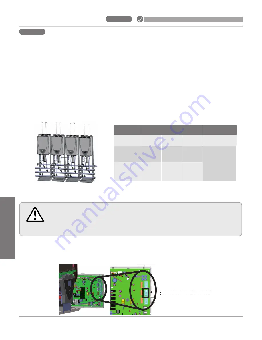
• The built-in Easy-Link System allows up to 2 units (160X3P and 180X3P) or 4 units (199X3P) to manifold
together. The table below shows the allowable combinations.
• The supplied communication cable (100076516) is required for linking.
• An Easy-Link system will have full modulation from 9,000 btu/h to the sum of maximum inputs of the
connected water heaters
• The priority heater is the heater that will be the first to activate when there is a call for demand. The
pump of the priority heater will be the one in operation during recirculation pump active periods.
The priority heater will rotate to the next number assigned heater based on either 12 hours of heater
operation time or 100 start/stop cycles, whichever comes first.
• In the Easy-Link System, one unit must be designated as a
PARENT
unit by changing the Parent/Child
DIP switch. Refer to the procedure below. The other unit(s) are
CHILD
units.
Hot Out
Gas In
Cold In
Return
Line
*Each CHILD unit is allocated the above number from controller, which indicates on the display of the controller on the unit. (Refer to p. 73.)
Type of unit
Model
Allocated No.
from controller
PARENT
160X3P 180X3P 199X3P
1
CHILD
160X3P 180X3P
199X3P
or
540
2,3,4*
Max.
Number
of child units
1
1
3
INSTALLATION
Step 18:
Easy-Link System
Step 18:
Easy-Link System
Change DIP switch setting
WARNING
• To change the DIP switch settings for the Easy-Link System, locate the MIDDLE bank of
DIP switches at the near side of the computer board of the PARENT unit.
• DO NOT adjust any other DIP switches .
• Turn off the power supply to the water heater before changing the DIP switch.
• Failure to observe this warning could result in carbon monoxide poisoning or death.
1. Turn off the power supply to the water heater.
2. After removing the front cover, remove the screw to pull out
the PCB.
3. Only change the
No.1 DIP switch
of the middle bank of the
parent
unit to the ON position. (Refer to the figure on p. 51.)
4. Put back the PCB into the unit and attach the removed screw
and reinstall the front cover.
Middle bank of DIP switches
Summary of Contents for 160X3P
Page 84: ...7J8071 1 2000570774 REV B...


