REP
AIR
PAR
T
On-Demand Water Heater Installation Manual and Owner’s Guide
77
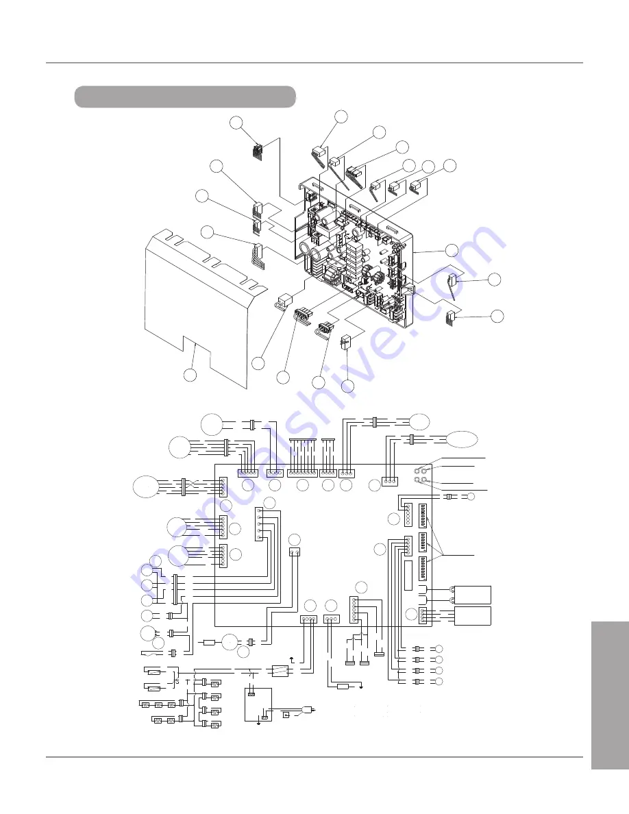
REPAIR PARTS
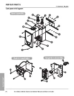
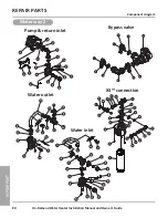
Component diagram
715
715
715
715
715
715
715
701
715
715
715
708
714
709
103
738
708
716
Computer board assembly
DIP switches
W
R
Pressure
Sensor
R W
BK
BK
BK W
R
Flow
Sensor
BK W
R
G
BL
Y
R
BR
R
O
Y
G
BL
W
BK
Wir
eless
Monit
oring
Flow
Adjust
Valve
R
BK
Bypass
Valve
R Y
WBL
BR
BR BL
W
Y
R
BK
R
Air damper
W Y
O R
BR
BR R
W
O
Y
W
Y BL
O
R
FM
W
Y
BL
O
R
Pump
MV
SV3
SV2
SV1
BR
G
LB
R
BL
O.H.C.F
BL
BL
Hi-
limit
BL
BL
BL
BR
BL
R
LB
G
IG
Igniter
rod
P
P
P
P
120 VAC
G
WBK
Surge
box
W BK
G
W
BK
Ground
SW
W
BK
Ground
Thermostat
Thermostat
Heater
Heater
Heater
Heater
Heater
Heater
BK
BK
BK
BK
BK
BK
Y
Y
Y
Y
Y
Y
Y
Y
Y
Flame
rod
Ground
Remote
controller
Built-in
controller
WBL
R BK
Exhaust thermistor
W
W
BK
BK
Return thermistor
Heat exchanger
thermistor
Inlet thermistor
Outlet thermistor
BK
BK
BK
BK
BK
BK
Y
G
Increase bu�on
Decrease bu�on
MAX bu�on
MIN bu�on
BL
BL
W: WHITE
R: RED
BK: BLACK
P: PURPLE
LB: LIGHT BLUE
BL: BLUE
G: GREEN
Y: YELLOW
O: ORANGE
BR: BROWN
6
5
4
3
2
1
7
ON
6
5
4
3
2
1
ON
6
5
4
3
2
1
8
7
ON
8
715
715
715
715
715
722
738
103
131
721
708
708
714
737
709
715
715
715
715
715
W
BK
Paren
t
WBK
W
BK
①
②
Easy-Link
9
53
73
Summary of Contents for 160X3P
Page 84: ...7J8071 1 2000570774 REV B...

