background image

41


Page

Normal Operation

Owner's Guide

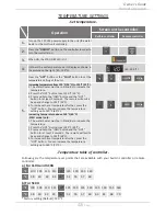
NORMAL OPERATION

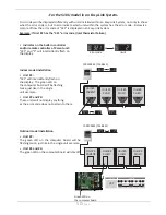
BUILT-IN CONTROLLER AND REMOTE CONTROLLER

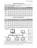
The illustration below shows an example of the controllers.  The exact display may differ from examples.

"COLD" Button

"HOT" Button

Press the "HOT" button or the "COLD" 

button to set the hot water temperature.

STAND BY LED (Orange)

The indicator is ON to show that 

power is ON.

IN USE LED (Green)

The


indicator lights during combustion.

"INFO" Button

Each time the button is pressed,

the operation mode is selected

in the sequence of the following.

Inlet water

temperature

Outlet water

temperature

Water

 flow

When the STAND BY LED is ON, the 

hot water temperature will be 

displayed.

Display for Temperature

"ON/OFF" Button

Press this button to 

start or stop operation.

Built-in controller

Remote controller

• 

When the remote controller is installed, it will take priority over the built-in controller.

• 

The controller has an energy saving mode.  Five minutes after the water heater stops 

operating, the backlight of the controller turns off. 

• 

The backlight of the remote will turn back on once the water heater begins firing again.

NOTICE

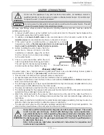
GENERAL

1.

 Open a cold water

fixture.

2.

 Mix hot water with the cold water 

to get the correct temperature water.

3.

 When finished, close the 

water fixtures.

• 

Flow rate to activate the water heater: 0.5 gallon per minute at the default set

temperature (1.9 L/min).

• 

Flow rate to keep the water heater running: 0.4 gallon per minute (1.5 L/min).

NOTICE

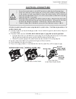
Temperatures above 125 °F (52  °C) can cause severe burns or death from scalding. 

Children, disabled and the elderly are at high risk of being injured.

WARNING

°F

120

125

130

135

140

145

150

155

°C

49

52

54

57

60

63

66

68

Time to produce 

serious burn

more 

than 5 

min.

1½ to 2 

min.

about

30 sec.

about

10 sec.

less than 

5 sec.

less than 

3 sec.

about

1½ sec.

about 

1 sec.

Summary of Contents for 200 Series

Page 1: ...ure reference whenever maintenance adjustment or service is required ANSI Z21 10 3 CSA 4 3 510U only Models 110U Outdoor 310U Outdoor 510U Outdoor 110U Indoor 310U Indoor 510U Indoor Series 200 Do not...

Page 2: ...7 Propane LP Supply Piping 27 WATER CONNECTIONS 28 Pressure relief valve 28 ELECTRICAL CONNECTIONS 29 TEMPERATURE REMOTE CONTROLLER 30 Included accessories 30 Installation 30 EASY LINK SYSTEM 32 Easy...

Page 3: ...Before use we recommend that you read through this installation manual carefully Keep this manual for future reference If you need an additional manual contact the manufacturer or your local distribut...

Page 4: ...rect vent type for outdoor installation are divided into four categories based on static pressure produced in the vent and flue loss Category I a water heater that operates with a non positive vent st...

Page 5: ...urners Hot water fixture Exhaust vent Heat exchanger Gas valves Fan motor Flow adjustment valve Computer board Thermistor Cold water inlet Hot water outlet Gas inlet Thermistor Burners Flow sensor Ign...

Page 6: ...e authority having jurisdiction Failure to follow instructions could result in property damage serious personal injury or death The agent performing this work assumes responsibility for this conversio...

Page 7: ...uding flour can clog the air intake and reduce the operation of the fan This in turn can cause improper combustion and reduce the life of the water heater Regularly ensure that the area around the wat...

Page 8: ...ed by water quality Only potable water can be used with this water heater Do not introduce pool or spa water or any chemically treated water into the water heater Water hardness levels must not exceed...

Page 9: ...Communication cable 510U only LP Conversion Kit 100270585 Qty 1 100209924 TM RE42 Qty 1 Qty 1 Manifold attachments 2 Small 1 Large Manifold gasket 100281157 1 Gas conversion sticker 1 Gas conversion...

Page 10: ...ation through a sidewall instead of two separate penetrations for the intake and exhaust piping The termination includes a bird screen restricting small animals pests and foreign objects from entering...

Page 11: ...debris that can be trapped inside the combustion chamber unless the system is direct vented The air intake must maintain a safe distance from the dryer s exhaust vent This will help to prevent lint f...

Page 12: ...ON No 4 ON Altitude DIP switches Installation altitude The maximum certified or allowable installed altitude is 10 100 ft 3 078 m for indoor models and 6 000 ft 1 829 m for outdoor models Outdoor mod...

Page 13: ...lation is prohibited Ensure that the installation location has sufficient clean combustion air If unsure direct vent the heater or refer to the Combustion Air Supply section below Direct venting insta...

Page 14: ...ormal amounts of carbon monoxide can result in seri ous injury or death Description Heater Vent Kits Z FLEX NovaVENT Z VENT 4 Straight pipe 6 length 100112407 2NVP4 5 2SVEPWCF0406 4 Straight pipe 12 l...

Page 15: ...r 20 000 Total 235 000 Example Gas Burning Appliance BTU h Rating Gas Water Heater Total Your appliances Does your installation space have sufficient combustion air Ventilation with outside air is rec...

Page 16: ...vents These events can cause unsatisfactory water heater performance The best solution is to direct vent the water heater or install an adequate number of make up air vents See Install with outside v...

Page 17: ...with the equipment so that they open automati cally during operation Keep louvers and grills clean and free of debris or other obstructions Check that air source is clean and free of chemicals Air for...

Page 18: ...1 in2 per 4 000 btu h Con ned Space 12 maximum Gable vent to outdoors Install above insulation Figure 5 SIngle opening Con ned Space 1 in2 per 3 000 btu h Alternative Opening Location Figure 6 Two pe...

Page 19: ...d in the installation the maximun length of exhaust vent pipe must not exceed 55 ft 16 8 m and the vent run must not exceed 5 elbows Vent termination kit 100187154 also has specific DIP switch setting...

Page 20: ...p 110U Indoor 310U Indoor 510U Indoor Upper bank of DIP switches Vent length No 6 O N No 7 OFF No 8 OFF No 3 O N No 4 OFF No 5 OFF 0 to 60 ft 0 to 18 3 m OFF ON 1 2 3 4 5 6 7 8 9 10 OFF ON 1 2 3 4 5 6...

Page 21: ...FF No 5 OFF 21 to 40 ft DEFAULT 6 2 to 12 2 m No 6 O N No 7 O N No 8 OFF No 3 ON No 4 ON No 5 OFF 41 to 60 ft 12 3 to 18 3 m OFF ON 1 2 3 4 5 6 7 8 9 10 OFF ON 1 2 3 4 5 6 7 8 OFF ON 1 2 3 4 5 6 7 8 9...

Page 22: ...lation DIP switch settings 110U Outdoor 310U Outdoor 510U Outdoor Upper bank of DIP switches No 6 OFF No 7 O N No 8 OFF No 3 OFF No 4 O N No 5 OFF OFF ON 1 2 3 4 5 6 7 8 9 10 OFF ON 1 2 3 4 5 6 7 8 Ou...

Page 23: ...Exhaust termination 2ft 610mm min Inside corner Anticipated Snow level 2ft 610mm min 1ft 305mm min 1ft 305mm min Combined intakeand exhaust termination Multiple Sidewall Terminations An exhaust termi...

Page 24: ...5 mm min Multiple flat roof terminations Exhaust gas Exhaust gas Intake air Intake air 1 ft 305 mm min 1ft 305mm min 1 ft 305 mm min 1 ft 305 mm min Anticipated snow level 1 ft 305mm min 2 ft 610 mm m...

Page 25: ...f center line extended above meter regulator assembly 3 ft 91 cm I Clearance to service regulator vent outlet Above a regulator within 3 ft 91 cm horizontally of the vertical center line of the regula...

Page 26: ...as leak test either by applying soapy water to all gas fittings and observing for bubbles or by using a gas leak detection device The water heater and its individual shutoff valve must be disconnected...

Page 27: ...th ft m Diameter in 10 3 0 20 6 1 30 9 1 40 12 2 50 15 2 60 18 3 70 21 3 80 24 4 90 27 4 100 30 5 125 38 1 150 45 7 200 61 0 1 2 172 118 95 81 72 65 60 56 52 50 44 40 34 3 4 360 247 199 170 151 137 12...

Page 28: ...pacity must be at least 140 000 BTU h for the 110U model 190 000 BTU h for the 310U model and 199 000 BTU h for the 510U model The pressure relief valve must be rated for a maximum of 150 psi 1 MPa Th...

Page 29: ...g instead of a junction box The following procedure is for outdoor models only 1 The water heater must be electrically grounded Do not attach the ground wire to either the gas or the water piping 2 Th...

Page 30: ...e Verify that the items listed below are included with the remote controller Temperature remote controller Screws Fork terminals Manual Remote controller cable Qty 1 Qty 2 Qty 4 Qty 1 Qty 1 Installati...

Page 31: ...t power supply from the water heater 2 Take off the water heater s front cover 3 Locate the two terminals for the remote controller in the water heater Refer to the Fig E 1 and E 2 4 Put the remote co...

Page 32: ...table above A remote controller is not required for an Easy Link System However it does provide for more temperature options and ease of maintenance If a remote controller is used the temperature on a...

Page 33: ...t will override the built in controller Built in controller for indoor models remote controller for outdoor models A 510U model Computer board WARNING To change the DIP switch settings for the Easy Li...

Page 34: ...dual cut off switch is recommend ed for each unit in a Multi Unit System for the purpose of maintenance Multi Unit System connection diagram Multi unit controller and temperature remote controller wir...

Page 35: ...uirements must be followed Toxic chemicals used in boiler treatments such as alcohol glycerol and glycol groups must not be introduced into the system The water heater can be used to supply combinatio...

Page 36: ...ates every 6 hours for 60 seconds Wire to product approved pump Heating Coil used with air handler Cold water supply 3 intake and 4 vent Discharge must comply with local and state codes Cannot be comm...

Page 37: ...heck for the presence of leaking gas toward the bottom of the unit because some gases are heavier than air and may settle toward the floor Check the GAS PRESSURE Refer to pp 26 and 46 Do not try to li...

Page 38: ...commend that you read through this owner s guide carefully Keep this manual for future reference If you need an additional manual contact the manufacturer or your local distributor When you call pleas...

Page 39: ...mpted repair may result in a fire or explosion D Do not use this appliance if any part has been under water Immediately contact a qualified installer or service agency to replace a flooded water heate...

Page 40: ...In approved containers 3 Tightly closed and out of reach of children 4 Water heater has a main burner which may come on at any time and will ignite flammable vapors Vapors 1 Cannot be seen 2 Are heavi...

Page 41: ...e controller is installed it will take priority over the built in controller The controller has an energy saving mode Five minutes after the water heater stops operating the backlight of the controlle...

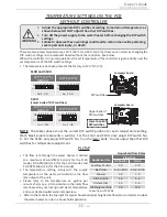
Page 42: ...ds The remote will emit a beep and change to 125 F 52 C 4 To increase the set temperature further press the HOT button You can increase the temperature setting up to 140 F 60 C Increasing temperature...

Page 43: ...ing the INFO button Water flow 4th press Press the INFO button to finish information mode Unit conversion mode Units of measure can be changed from Imperial to Metric and vice versa For example temper...

Page 44: ...ry to 120 F 50 C DIP switches Computer board 110U and 310U 120 F 50 C DEFAULT 140 F 60 C No 9 OFF No 9 ON OFF ON 1 2 3 4 5 6 7 8 9 10 OFF ON 1 2 3 4 5 6 7 8 9 10 Lower bank of DIP switches Computer bo...

Page 45: ...your heater This will keep your unit from freezing and being damaged Normal Operation Owner s Guide Only pipes within the water heater are protected by the freeze protection system Any water pipes ho...

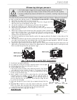
Page 46: ...port which is located on the gas inlet of the water heater shown in the diagram on the right 3 Connect the manometer to the pressure port and zero the manometer 4 Re open the manual gas valve Verify...

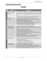
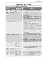
Page 47: ...opened Make sure the unit has 120 VAC 60 Hz power supply Is the power button on the controller or inside the water heater turned on Is the gas supply valve open fully p 37 Is the water supply valve op...

Page 48: ...roller and remote controller Built in and remote controller do not display anything when the power button is turned on Make sure the unit is supplied with power For the remote controller Make sure the...

Page 49: ...ilt in controller and or remote controller 321 will be displayed on the screen Green LED on the computer board The green LED on the computer board will indicate this code with two flashes every 1 2 se...

Page 50: ...he display Unit Error code 100209924 TM RE42 Unit 1 PARENT Unit 2 CHILD Unit 4 CHILD Unit 3 CHILD 100209924 TM RE42 Unit 1 PARENT Unit 2 CHILD Unit 4 CHILD Unit 3 CHILD Error code Green LED on on on o...

Page 51: ...mpty Check if there is a buzzing spark ignition sound coming from the burner Part 101 when water heater prepares for combustion Listen for the double clunk sound coming from the gas valve assembly Par...

Page 52: ...codes 721 Six Flashes False flame detection Check if condensate drain is installed on the vent collar of the water heater Check if there is leaking from heat exchanger Part 401 741 N A Miscommunicatio...

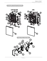
Page 53: ...MPONENTS DIAGRAM Components Diagram Owner s Guide Case assembly 006 004 052 052 003 052 003 001 001 005 007 007 715 002 052 050 704 052 050 050 050 704 710 008 008 002 Built intemperaturecontroller 72...

Page 54: ...705 103 402 402 707 713 403 714 709 708 711 705 103 709 402 402 711 707 714 407 408 708 701 064 713 712 712 721 721 Computer board assembly Surge box assembly Components Diagram Owner s Guide 120 705...

Page 55: ...08 401 150 117 116 121 062 114 701 102 119 101 107 707 152 151 057 063 062 062 067 062 055 056 052 055 053 111 113 061 110 711 711 714 053 053 057 060 109 115 054 702 053 108 104 122 122 104 053 053 0...

Page 56: ...417 461 401 460 456 458 458 414 416 451 414 451 402 404 407 406 405 460 456 458 461 052 415 058 454 457 052 D 408 410 409 415 058 454 455 052 C 401 To Water inlet section D To Water outlet section C 4...

Page 57: ...3 Pan head Screw M3x6 SUS3 Binding head Pan screw M4x8 MFZN Tapping screw M4x14 SUS410 Truss head Screw M3x12 BSNI Raised counter sunk head 100074512 100074272 100074514 100074244 100076450 100074515...

Page 58: ...EKK2B EKK2C 407 Inlet thermistor for 110U and 310U Inlet thermistor for 510U 100074398 100224109 EKK4J EK573 408 Outlet thermistor for 110U and 310U Outlet thermistor for 510U 100074680 100224110 EK20...

Page 59: ...Power ON OFF switch N A N A EK614 EK590 707 708 Remotecontrollerwirefor110Uand310U for 510U Gas valve wire 100074649 100074650 N A EK189 EK165 EK585 709 710 711 Flame rod wire Cable strap Igniter ass...

Page 60: ...ter GPM SetTemp F Incoming Temp F When the set temperature is 130 F 55 C or higher maximum flow rate is limited to 8 0 GPM 510U Output Temperature vs GPM Max 10 0 GPM with Various Inlet Water Temperat...

Reviews: