28
Page
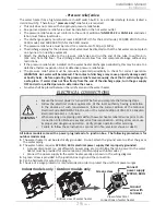
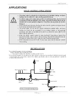
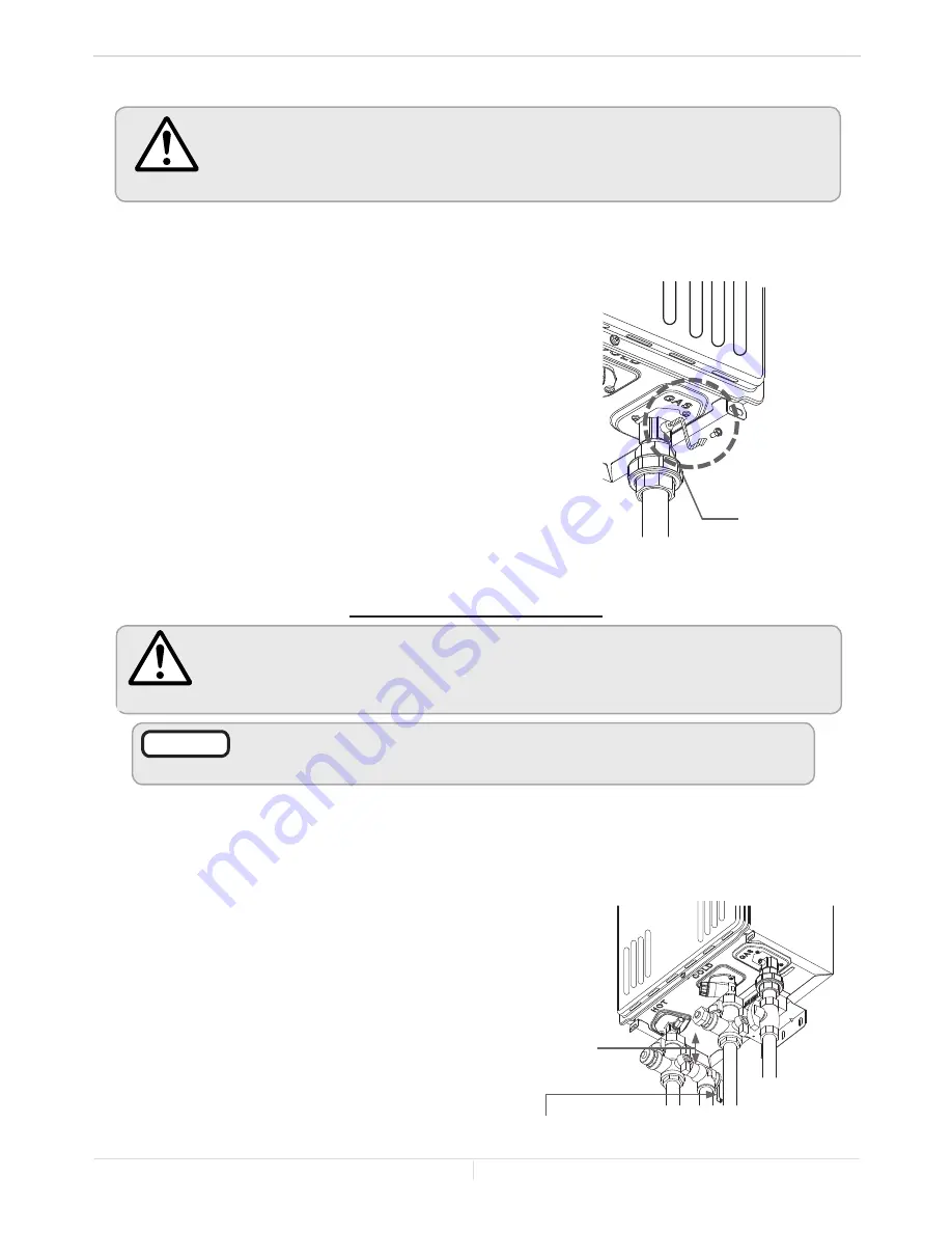
Pressure port
Cold
inlet
Hot
outlet
Gas
inlet
As Close as
Possible
Pressure relief valve
Installation
Installation Manual
-Measuring inlet gas pressure-
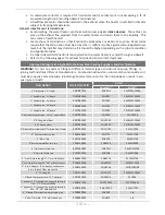
The water heater cannot perform properly without sufficient inlet gas pressure. Below are instructions
on how to check the inlet gas pressure.
THIS IS ONLY TO BE DONE BY A LICENSED PROFESSIONAL
.
1.
Shut off the manual gas valve on the gas supply line.
2.
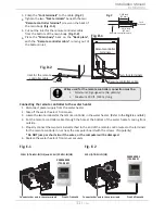
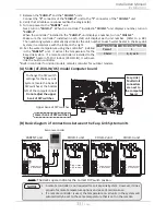
Remove the screw for the pressure port located on the gas inlet of
the water heater shown in the diagram on the right.
3.
Connect the manometer to the pressure port.
4.
Re-open the manual gas valve. Verify that there are no gas leaks.
5.
With all gas burning equipment off, take a reading of the static gas
pressure.
6.
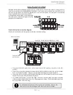
Measure gas supply pressure at maximum heater operation: Open
up water faucets to create maximum flow. Press and hold the
MAX button on the computer board. Take a reading of the supply
dynamic gas pressure with all gas burning equipment running at
maximum rate.
7.
The static and dynamic pressures should be within the ranges
specified on the heater's rating plate and the table on p. 26.
8.
The difference of static to dynamic pressure should not exceed
1.5" W.C. Pressure drops that exceed 1.5" W.C. can indicate
restricted gas flow, undersized gas lines, and/or undersized supply regulators.
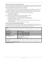
1. Turn off all electric power to the water heater if service is to be performed.
2. Turn the manual gas valve located on the outside of the unit to the OFF position.
WARNING
•
Do not use this water heater if any part has been submersed under water. Do not attempt
to repair the unit. It must be replaced. Failure to follow these instructions could lead to
property damage, personal injury, or loss of life.
WARNING
•
Do not reverse the hot outlet and cold inlet connections to the water heater.
This will not activate the water heater properly.
NOTICE
4. Before installing the water heater, flush the
water line to remove all debris, and after
installation is complete, purge the air from
the line. Failure to do so may cause damage
to the water heater.
5. There is a wire mesh filter within the cold
inlet to trap debris from entering your heater.
This will need to be cleaned periodically to
maintain optimum flow. (Refer to p. 46.)
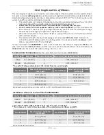
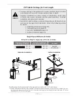
All pipes, pipe fittings, valves and other components, including soldering materials, must be suitable for
potable water systems.
1. A manual shutoff valve must be installed on the cold water inlet to the water heater between the
main water supply line and the water heater.
2. In addition,
a manual shutoff valve
is also recommended on the hot water outlet of the unit.
Isolation valves
are recommended as shown in the picture at right.
3. If the water heater is installed within, or subjected to, a closed
loop water system,
a thermal expansion tank must be installed to
handle thermal expansion.
WATER CONNECTIONS
Summary of Contents for AT-KJr3U-IN
Page 63: ...63 Page This page is intentionally left blank...
Page 64: ...1W1101 100269776...

