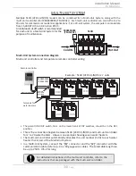
31
Page
Installation
Installation Manual
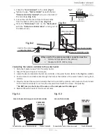
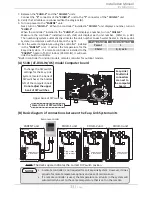
3. Crimp the
"Fork terminals"
to the cable.
(Fig. C)
4. Tighten the two
"Fork terminals"
beneath the two
"Remote controller terminal"
screws on the back of
the main body.
(Fig. D-1)
5. Cut out the inlet for the remote controller cable
from the bottom of the main body.
(Fig. D-2)
6. Place the
"Main body"
back on the
"Back plate"
,
with the
"Remote controller cable"
running out of
the bottom inlet.
Remote controller
terminals
Fig. D-1
Two fork terminals
Remote controller cable
Inlet for the remote
controller cable
Cut out
Fig. D-2
Remote controller cable
1-3/8 Inch
(35 mm)
Fig. C
1-5/8 Inch
(41 mm)
Fork
Terminals
Connecting the remote controller to the water heater
1. Disconnect power supply from the water heater.
2. Take off the water heater’s front cover.
3. Locate the two terminals for the remote controller in the water heater. (Refer to the
Fig. E-1
and
E-2
.)
4. Put the remote controller cable through the hole at the bottom of the water heater's casing from
outside.
5. Properly connect the two terminals attached to the end of the remote control wires to the terminals
for the remote controller on or near the computer board with the screws. (No polarity)
* Do NOT jump or short-circuit the wires, or the computer will be damaged.
6. Replace the water heater's front cover securely.
Wires used for the remote controller connection must be:
•
Minimum 20
gauge wire (No polarity)
•
Maximum 400 ft. (122 m) long
110U (AT-KJr3U-IN/OS) and 310U (AT-K5U-IN/OS)
9009069005
(TM-RE42)
Front of remote
Connect other end to these terminals
Fig. E-1
9009069005
(TM-RE42)
Front of remote
Connect other end to these terminals
510U (AT-D3U-IN/OS)
Fig. E-2
Summary of Contents for AT-KJr3U-IN
Page 63: ...63 Page This page is intentionally left blank...
Page 64: ...1W1101 100269776...

