background image

Installation


31

Page


Connecting


two


MASTER


connectors”


together


from


two


separate


units


may


damage


the


computer


board

.


The


communication


cable


has


a


female


end


and


a


male


end


so


it’s


impossible


to


have


a


MASTER

  ‐

to

‐ 

MASTER


connection


with


the


communication


cable.


Do


not


splice


or


modify


connectors.


The


TM

RE30


is


not


required


for


the


Easy

Link


system.


If


running


the


Easy

Link


system


without


the


TM

RE30,


please


make


sure


the


temperature


settings


on


ALL


the


units


are


set


to


the


same


settings.


Otherwise,


the


units


may


not


operate


properly.


If


the


TM

RE30


is


used,


the


temperature


on


all


the


units


in


the


system


will


automatically


be


set


to


the


same


temperature


that


is


set


on


the


remote.


CASE


3:


If


you


connect


the


“MASTER


connector”


of


the


“SLAVE

1”


unit


to


the


“[1]


connector”


of


the


“SLAVE

2”


unit

,


the


“SLAVE

2”


unit


will


operate


as


an


individual


unit,


and


will


not


be


part


of


the


Easy

Link


system.


CASE


4:


If


a


TM

RE30


remote


controller


(optional)


is


used,


it


has


to


be


connected


to


the


MASTER


unit.


If


the


TM

RE30


is


connected


to


a


SLAVE


unit,


it


will


only


control


that


particular


individual


SLAVE


unit


and


will


not


control


the


Easy

Link


system


as


a


whole.


Prohibited


Wrong


connection


between


the


“SLAVE

1”


unit

and


the


“SLAVE

2”


unit

TM-RE30


connected


to


incorrect


unit


WARNING

MASTER


unit


SLAVE


unit

C o n n e c t o r s

M

A

S

T

E

R

2

1

M

A

S

T

E

R

2

1

O

F

F

O

N

1

2

3

4

5

6

7

8

R i g h t   b a n k   o f
D i p s w i t c h e s

O

F

F

O

N

FREEZE

MODE

RE-CIR

STORAGE

1

2

3

4

5

6

7

8

D-PRT

MASTER

9

1

0

C o m m u n i c a t i o n   c a b l e

C o n n e c t o r s

M

A

S

T

E

R

2

1

M

A

S

T

E

R

2

1

O

F

F

O

N

1

2

3

4

5

6

7

8

R i g h t   b a n k   o f
D i p s w i t c h e s

O

F

F

O

N

FREEZE

MODE

RE-CIR

STORAGE

1

2

3

4

5

6

7

8

D-PRT

MASTER

9

1

0

CELSIUS

CELSIUS

C o n n e c t o r s

M

A

S

T

E

R

2

1

M

A

S

T

E

R

2

1

O

F

F

O

N

1

2

3

4

5

6

7

8

R i g h t   b a n k   o f
D i p s w i t c h e s

O

F

F

O

N

FREEZE

MODE

RE-CIR

STORAGE

1

2

3

4

5

6

7

8

D-PRT

MASTER

9

1

0

C o n n e c t o r s

M

A

S

T

E

R

2

1

M

A

S

T

E

R

2

1

O

F

F

O

N

1

2

3

4

5

6

7

8

R i g h t   b a n k   o f
D i p s w i t c h e s

O

F

F

O

N

FREEZE

MODE

RE-CIR

STORAGE

1

2

3

4

5

6

7

8

D-PRT

MASTER

9

1

0

C o m m u n i c a t i o n   c a b l e

C o n n e c t o r s

M

A

S

T

E

R

2

1

M

A

S

T

E

R

2

1

O

F

F

O

N

1

2

3

4

5

6

7

8

R i g h t   b a n k   o f
D i p s w i t c h e s

O

F

F

O

N

FREEZE

MODE

RE-CIR

STORAGE

1

2

3

4

5

6

7

8

D-PRT

MASTER

9

1

0

CELSIUS

CELSIUS

CELSIUS

MASTER


unit


SLAVE

1


unit

SLAVE

2


unit


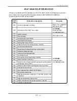
Summary of Contents for T?H2?DV

Page 1: ...le water heating and space heating TAKAGI Industrial Co USA Inc 5 Whatney Irvine CA 92618 Toll Free 888 882 5244 USA Toll Free 877 877 4953 CANADA This product must be installed and serviced by a licensed plumber a licensed gas fitter or a professional service technician Improper installation and or operation or installation by an unqualified person will void the warranty If the information in thi...

Page 2: ... High altituderegionsupportfunctions T H2 OS Installation T H2 DV Installation Venting Instructions Gas Supply Gas Pipe Sizing Water Connections Pressure Relief Valve Condensate drain Electrical Connections Remote Controller Connection Pump Control Connection Pump Control Mode Easy Link System APPLICATIONS Space Heating INITIAL OPERATION OPERATING SAFETY NORMAL OPERATION General Temperature settin...

Page 3: ...igned to efficiently supply endless hot water for your needs The principle behind the T H2 DV T H2 OS Water Heater is simple 1 A hot water tap is turned on 2 Water enters the heater 3 The water flow sensor detects the water flow 4 The computer automatically ignites the burner 5 Water circulates through the heat exchanger and then gets hot 6 The computer will modulate the gas supply valve and water...

Page 4: ...nger is damaged due to freezing Refer to the section on the Freeze Prevention System on p 39 for more information SAFETY GUIDELINES GENERAL 1 Follow all local codes or in the absence of local codes follow the most recent edition of the National Fuel Gas Code ANSI Z223 1 NFPA 54 in the USA or CAN CSA B149 1 Natural Gas Propane Installation Code in Canada 2 Properly ground the unit in accordance wit...

Page 5: ...n etc Locate your heater close to a drain where water leakage will not do damage to surrounding areas As with any water heating appliance the potential for leakage at some time in the life of the product does exist Takagi will not be responsible for any water damage that may occur If you install a drain pan under the unit ensure that it will not restrict the combustion air flow T H2 DV T H2 OS are...

Page 6: ...ild up within the fan and burner causing damage to the unit 6 Particles from flour aerosols and other contaminants may clog the air vent or reduce the functions of the rotating fan and cause improper burning of the gas Regularly ensure that the area around the unit is dust or debris free regular maintenance is recommended for these types of environment 7 Do not install the unit where the exhaust v...

Page 7: ...sual aspects of the whole installation for the water heater 3 TK KPWL4 and TK KPWH4 T Vent Wall thimble with Termination These terminations are used when venting out through the wall and are compatible with the T Vent pipe system These terminations are special stainless steel vents for gas appliances and are UL listed as Category II III and IV There are two types of terminations the Louver termina...

Page 8: ...an accumulate Do not install this water heater under an overhang less than 3 feet from its top or eaves The area under an overhang must be open to three sides T H2 OS only Do not install the water heater vent terminator within 1 ft in the USA of any air intake or building opening and with in 3 ft in Canada of any air intake or building opening T H2 OS only Refer to p 15 Do not install next to a dr...

Page 9: ...on where your water heater is installed Set dipswitches shown in the table below depending on the altitude These dipswitches No 5 and No 6 are on the computer board on the left bank only 0 to 2 500 ft DEFAULT Over 5 000 ft Switch No 5 OFF ON OFF Consult TAKAGI Technical Dept at 1 888 882 5244 Switch No 6 OFF OFF ON T H2 OS INSTALLATION 1 Install the T H2 OS only in areas with mild temperate climat...

Page 10: ...ntake pipe must be sealed airtight Air supply pipe can be made of ABS PVC galvanized steel corrugated stainless steel or Category lll IV stainless steel Sidewall venting is recommended for the T H2 DV Vertical venting roof termination is acceptable TAKAGI recommends running the exhaust vent and the intake pipe as parallel as possible The TH PA01 adaptor is used to make the connection between the T...

Page 11: ...r each elbow added deduct 5 ft from max Vent length No of Elbows Max Vertical or Horizontal Length 0 50 ft 1 45 ft 2 40 ft 5 25 ft For details on the vent connection to the T H2 DV refer to P 13 Exhaust vent Stainless steel vent This is a Category IV appliance and must be vented accordingly The vent system must be sealed air tight All seams and joints without gaskets must be sealed with high heat ...

Page 12: ... recommended when the water heater is vented through a sidewall General rules for venting the T H2 DV water heater are 1 Place the water heater as close as possible to the vent terminator 2 The vent collar of the water heater must be fastened directly to an unobstructed vent pipe or TH PA01 adaptor 3 Do not weld the vent pipe to the water heater collar 4 Do not cut the vent collar of the unit 5 Th...

Page 13: ...tinue on the rest of the vent run with 4 PVC pipe Horizontal Installation Diagram Vertical Installation Diagram Roof Flashing Roof Fire stop Connection between exhaust vent collar and PVC piping See below for instructions Wall Exhaust vent collar of the T H2 DV Female TH PA01 PVC adaptor 4 PVC coupler 4 PVC Straight pipe TH PA01 PVC adaptor is included with the T H2 DV Connection between exhaust v...

Page 14: ...llow all vent system manufacturer s instructions and all local codes Do not common vent or connect any vent from other appliances to the T H2 DV vent Use 4 Category III IV approved or Special BH single or double wall stainless steel vent pipe Vertical Installation Diagram Horizontal Installation Diagram Wall Sidewall Vent Terminator Roof Flashing Roof Rain Cap Fire stop ...

Page 15: ...rance to outside corner G Clearance to inside corner H Clearance to each side of center line extended above meter regulator assembly 3 feet I Clearance to service regulator vent outlet 3 feet J Clearance to non mechanical air supply inlet to building or the combustion air inlet to any other application 3 feet 1 foot 4 feet from below or side opening 1 foot from above opening K Clearance to mechani...

Page 16: ...nd exhaust into a single penetration space each direct vent termination at least 1 ft away from each other no matter the orientation A direct vent termination must also be at least 2 ft away from an inside corner if the adjacent wall is less than 2 ft of length the minimum required distance away from the inside corner will be equal to the length of that adjacent wall For multiple unit rooftop term...

Page 17: ... Inlet gas pressure Natural Gas Min 5 0 WC Max 10 5 WC Propane Gas Min 8 0 WC Max 14 0 WC 2 Gas pressure below this specified range for the T H2 DV T H2 OS and or insufficient gas volume will adversely affect performance These pressures are measured when the T H2 DV T H2 OS is in full operation 3 Inlet gas pressure must not exceed the above maximum values gas pressure above the specified range wil...

Page 18: ... Natural Gas Supply Piping Maximum Delivery Capacity of Cubic Feet of Gas per Hour of IPS Pipe Carrying Natural Gas of 0 60 Specific Gravity Based on Pressure Drop of 0 5 WC Based on Energy Content of 1000 BTU Cubic Ft T H2 DV T H2 OS requires 199 Cubic Ft hr Unit Cubic Feet per Hour Pipe Size Length in Feet Inches 10 20 30 40 50 60 70 80 90 100 125 150 200 363 249 200 171 152 138 127 118 111 104 ...

Page 19: ...t by 1000BTU to get the appliances Cubic Ft requirement Takagi into account the distance the appliance is from the gas meter look in the above gas chart to properly size the line For sections of the gas line supplying gas to more than one appliance Ex Point A to Point B add up the cubic ft requirements of the appliances that are being supplied by that section and size to the farthest appliance For...

Page 20: ...ny restrictions 8 If the pressure relief valve installed on the T H2 DV T H2 OS discharges periodically this may be due to a defective thermal expansion tank or defective pressure relief valve 9 The pressure relief valve must be manually operated periodically to check for correct operation CONDENSATE DRAIN The T H2 DV T H2 OS does not include a built in condensate neutralizer cartridge for reducin...

Page 21: ...ired installing the TH NT01 Neutralizer assembly 1 Connect the 1 2 FPT X 3 8 MPT Adaptor to the condensate drain port at the bottom of the T H2 DV T H2 OS 2 Connect the TH NT01 Neutralizer to the 3 8 MPT connection of the adaptor There is a flow direction indicator on the neutralizer Please orient the neutralizer in the proper direction 3 Connect a 1 2 drain tube to the other end of neutralizer 4 ...

Page 22: ...etely consumed Condensate will remain acidic and can possibly cause damage to items such as pipes concrete etc if drained improperly The TH NT01 Neutralizer cartridge is designed to last for 3 years before replacement However the actual life of the neutralizer may vary depending on the application and usage Please ensure that the cartridge is properly replaced before the neutralizer elements have ...

Page 23: ...TRICAL CONNECTIONS 1 The T H2 DV T H2 OS must be electrically grounded Do not attach the ground wire to either the gas or the water piping 2 The T H2 DV T H2 OS requires AC 120V 60 Hz electrical power supply that is properly grounded A proper disconnect i e on off switch power plug etc controlling the main power to the T H2 DV T H2 OS must be provided for service reasons Must comply with local cod...

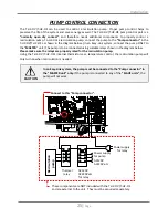
Page 24: ...the terminals are firmly fixed 5 Pull the remote s wires through the rubber grommet at the bottom of the water heater s casing 6 Properly attach the remote s wires to the remote controller terminal on the computer board No polarity Do NOT jump 7 Replace Front Cover securely 8 Wires used for the remote controller connection must be Minimum 18AWG wire No polarity Maximum 400 feet long Remote control...

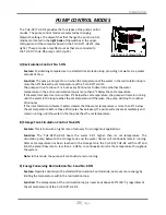
Page 25: ...on pump connect the pump to the Pump connector in the T H2 DV T H2 OS as shown in the diagram below In an Easy Link system connect the pump ONLY to the MASTER unit The pump is to be connected using suitable relays shown in the diagram below Please make sure the relays are properly rated for the recirculation pump Using the T H2 DV T H2 OS s internal thermistors as a temperature control the recircu...

Page 26: ...t temperature Otherwise the pump will stop for another 30 minutes If the inlet thermistor of water heaters detects that the water temperature is more than 9 F below the set temperature before those 30 minutes have elapsed the pump will activate immediately and remain running until the water in the loop reaches the set temperature B Storage Tank Circulation Control No 6 ON Feature This is to ensure...

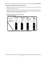
Page 27: ...en the TM RE30 remote is turned off Water in the loop will be maintained at the set temperature of the water heater Switch No 5 ON OFF ON OFF Switch No 6 OFF ON ON OFF The dark squares indicate the direction the dipswitch should be set to B Storage Tank Circulation Control C Energy Conserving Recirculation A Recirculation Control 1 2 3 4 5 6 7 8 N O 9 10 N O 1 2 3 4 5 6 7 8 9 10 D Normal Control D...

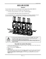
Page 28: ... communication cable gray color comes with each unit You can manifold from 2 to 4 units without the need for a multi system controller A 4 unit system has full automatic modulation between 13 000 BTU h and 796 000 BTU h Easy Link Connection Procedures 1 Verify the set temperatures of all units within the system Every single T H2 DV T H2 OS must be set to the same set temperature 2 Select one unit ...

Page 29: ...H2 OS Computer board B Basic diagram of connections among the T H2s Right bank of dipswitches Left bank of dipswitches When setting a unit to a MASTER unit adjust dipswitch No 10 on the right bank of dipswitches only see diagram Easy Link connectors are next to the computer board MASTER unit SLAVE 1 unit SLAVE 2 unit 3 digit 7 Seg LED Connectors MASTER 2 1 MASTER 2 1 OFF ON 1 2 3 4 5 6 7 8 Right b...

Page 30: ...s MASTER unit SLAVE 1 unit Wrong dipswitch setting on the MASTER unit Wrong connection between the MASTER unit and the SLAVE 1 unit C Examples of incorrect settings and or connections Connectors MASTER 2 1 MASTER 2 1 OFF ON 1 2 3 4 5 6 7 8 Right bank of Dipswitches OFF ON FREEZE CELSIUS MODE RE CIR STORAGE 1 2 3 4 5 6 7 8 D PRT MASTER 9 10 Connectors MASTER 2 1 MASTER 2 1 OFF ON 1 2 3 4 5 6 7 8 Ri...

Page 31: ... unit If the TM RE30 is connected to a SLAVE unit it will only control that particular individual SLAVE unit and will not control the Easy Link system as a whole Prohibited Wrong connection between the SLAVE 1 unit and the SLAVE 2 unit TM RE30 connected to incorrect unit WARNING MASTER unit SLAVE unit Connectors MASTER 2 1 MASTER 2 1 OFF ON 1 2 3 4 5 6 7 8 Right bank of Dipswitches OFF ON FREEZE M...

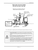
Page 32: ...ng appliances When the system requires water for space heating at temperatures higher than required for other uses a means such as a mixing valve shall be installed to temper the water for those other uses in order to reduce scald hazard potential Water temperature over 125 F can cause severe burns instantly or death from scalds Chemicals such as diluted Glycol can be used for radiant floor Hydro ...

Page 33: ...water heater and heating panel Heating Coil used with air handler Diagramatic Layout of Radiant Heating and Domestic Water Heater Per Mass Code Thermometer Check Valves Gas Inlet Drain Plug Water Filter 120 VAC Switch or Outlet The circulation pump is to provide no less than 2 GPM through each activated Takagi unit in the system Priority Control Devices such as a flow switch an Aquastat or other e...

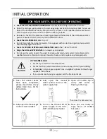
Page 34: ...ockets Do not use this water heater if any part has been submersed under water Immediately call a qualified service technician to inspect the water heater and to replace any damaged parts INITIAL OPERATION 1 Once the above checks have been completed please clean filter of any debris Refer to p 40 for instructions 2 Fully open the manual water control valve on the water supply line 3 Open a hot wat...

Page 35: ...ed or attempted repair may result in a fire of explosion D Do not use this water heater if any part has been under water Immediately call a qualified service technician to inspect the water heater and to replace any damaged parts OPERATING INSTRUCTIONS 1 STOP Read the safety information above or in the Owners Manual 2 Turn off all electric power to the water heater 3 Do not attempt to light the bu...

Page 36: ...RNING The outlet hot water temperature of the T H2 DV T H2 OS water heater is factory set at 120 F Use this heater at your own risk The set outlet water temperature can cause severe burns instantly or death from scalds Test the water before bathing or showering Do not leave children or an infirm person in the bath unsupervised DANGER Hot Water Heater temperature over 125 F can cause severe burns i...

Page 37: ...n per minute Hot Water temperatures over 125 F can cause severe burns instantly or death from scalding The outlet hot water temperature of the T H2 DV T H2 OS water heater is factory set at 120 F Feel the water temperature before bathing or showering NORMAL OPERATION GENERAL 1 Open a hot water tap 2 Mix cold water with the hot to get the correct temperature water 3 Close the hot water tap WARNING ...

Page 38: ... the left side of the 3 digit 7 Seg LED will blink to indicate that the unit is working How to set the hot water temperature of the water heater 1 Take off the T H2 DV T H2 OS s front cover 2 Press the either Increase button or the Decrease button on the computer board to increase or decrease the set temperature The 3 digit 7 Seg LED will display the available set temperatures Figure 1 3 Scroll to...

Page 39: ...d with freezing For this freeze protection system to operate there has to be electrical power to the unit Damage to the heat exchanger caused by freezing temperatures due to power loss is not covered under the warranty In cases where power losses can occur consider the use of a backup power supply The freeze protection system will activate when the surrounding and or outside temperatures drop belo...

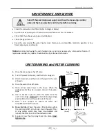
Page 40: ...needed any repairs should be done by a licensed technician UNIT DRAINING and FILTER CLEANING 1 Close the manual gas shut off valve 2 Turn off power to the unit and then turn on again 3 Wait 30 seconds and then turn off power to the unit yet again 4 Close the water shut off valve 5 Open all hot water taps in the house When the residual water flow has ceased close all hot water taps 6 Have a bucket ...

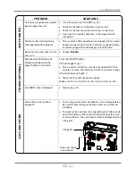
Page 41: ...ture set too high p 37 38 The hot water is not available when a fixture is opened Make sure the unit gets 120V 60Hz power supply If you are using the remote controller is the power button turned on Is the gas supply valve fully open p 34 Is the water supply valve fully open p 34 Is the filter on cold water inlet clean p 40 Is the hot water fixture sufficiently open to draw at least 0 5 GPM through...

Page 42: ...PTIONAL Remote controller does not display anything when the power button is turned on Press the ON OFF button If the lamp lights up This is normal When the unit has not operated for five minutes or more the display turns off to converse energy If the lamp does not light Make sure the unit has power supply Make sure the connection to the unit is correct p 24 An ERROR code is displayed Please see p...

Page 43: ...et thermistor failure Water heater It will display 321 on the 7 Seg LED TM RE30 It will display 321 on its screen Easy Link system The 7 Seg LED of the individual unit with the error in question displays the whole 3 digit error code The TM RE30 if installed displays a 3 digit number which signifies which unit has the error and what the error code is Example If Unit 2 has the 321 error code inlet t...

Page 44: ...TAKAGI Technical Dept at 1 888 882 5244 321 Inlet thermistor failure 331 Mixing thermistor failure 341 Exhaust thermistor failure Only T H2 DV 391 Air fuel Ratio Rod Failure 441 Flow Sensor Failure Only Easy Link system 510 Abnormal Main Gas Valve 551 Abnormal Gas Solenoid Valve 611 Fan Motor Fault 621 Exhaust fan motor Fault Only T H2 DV 631 Abnormal External Pump 651 Water Control Valve Fault Fl...

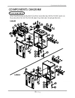
Page 45: ...ll of the T H2 OS s parts are the same as the T H2 DV The T H2 OS doesn t have fan motor for exhaust No 124 T H2 DV T H2 OS 001 007 054 006 703 052 004 003 052 702 152 005 002 051 008 009 004 152 052 011 012 013 014 010 052 152 152 124 152 704 015 007 054 006 703 052 004 702 152 005 016 051 008 009 004 152 052 010 052 ...

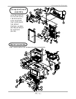
Page 46: ...hermistor assembly No 706 and exhaust fan motor wire No 720 Computer board assembly 101 102 103 104 105 106 107 108 109 110 111 112 114 116 117 118 119 120 121 122 123 151 152 152 152 152 710 152 152 155 155 054 153 128 053 705 152 113 712 710 708 154 125 709 423 710 720 114 711 704 705 706 707 708 701 712 152 713 714 715 716 055 717 053 053 055 053 713 711 715 719 704 For T H2 DV 719 For T H2 OS ...

Page 47: ...ly No 706 T H2 OS T H2 DV 456 152 459 460 461 152 152 A 401 402 403 404 407 408 409 410 411 412 413 414 415 416 417 418 419 420 414 421 422 423 424 425 428 414 429 414 436 430 432 433 419 434 435 438 440 441 442 706 445 052 419 414 420 443 437 405 446 B B 448 152 052 427 427 420 452 A C 414 420 406 450 417 426 450 417 455 452 455 150 437 443 431 C 451 150 437 443 152 453 152 127 126 405 454 454 45...

Page 48: ... Heat exchanger protection plate Left 016 EKH61 Front cover for T H2 OS 051 EW000 Screw M4 12 W Washer 128 EK042 O ring P20 NBR 052 EW002 Screw M4 10 Coated 150 EW012 Screw M4 8 053 EX010 Pan screw M4 10 151 EW00D Pan screw M4 8 054 EW02B Screw M4 10 152 EW003 Screw M4 10 055 EW023 Pan screw M3 10 153 EW00H PanscrewM4 12 W Washer 101 EKH5W Burner assembly 154 EW006 Pan screw M4 10 102 EKK2X Burner...

Page 49: ...5 Hot pipe 702 EM296 Transformer 431 EX137 Joint elbow 703 EKJ66 Junction box inner plate 432 EKN34 Hi limit switch 704 EKH6K Freeze protection and EH IG wire for T H2 DV 433 EKK2T Output thermistor 434 EKH30 Fastener 4 11 705 EKH6V Gas valve wire 435 EKJ02 Water outlet 706 EKH6E Exhaust thermistor assembly 436 EZH17 O ring JASO 1017 FKM 707 EKH6J Thermistors wire 437 EZF14 O ring P14 FKM 708 EKK1...

Page 50: ... 40 F 6 1 5 6 5 2 4 9 4 6 4 3 4 1 3 8 3 7 3 3 3 0 2 9 2 8 2 7 2 6 2 5 50 F 7 3 6 6 6 1 5 6 5 2 4 9 4 6 4 3 4 1 3 7 3 3 3 2 3 0 2 9 2 8 2 7 60 F 9 0 8 1 7 3 6 6 6 1 5 6 4 8 4 8 4 6 4 1 3 7 3 5 3 3 3 2 3 0 2 9 70 F 9 0 9 0 9 0 8 1 7 3 6 6 4 8 4 8 4 8 4 6 4 1 3 8 3 7 3 5 3 3 3 2 100 105 110 115 120 125 130 135 140 150 160 165 170 175 180 185 Output Hot Water GPM When the set temperature is 130 F or h...

Page 51: ... INCLUDING PROPERTY DAMAGE PERSONAL DAMAGES LOSS OF USE OR INCONVENIENCE SOME STATES DO NOT ALLOW THE EXCLUSION OR LIMITATION OF INCIDENTAL OR CONSEQUENTIAL DAMAGES SO THE ABOVE LIMITATION MAY NOT APPLY TO YOU 3 Warranty for models T H2 DV T H2 OS Unit Year Application HX 1 Parts Labor Single Family Domestic Hot Water No Recirculation 10 5 1 3 On Demand Recirculation 2 w Standard Recirculation Aqu...

Page 52: ...bed in the installation manual Condensate damage due to improperly installed or lack of a condensate trap drain Any Takagi product not installed in compliance with all applicable local state codes ordinances and good trade practices Any Takagi product sold to or installed in areas outside of the fifty states and the District of Columbia of the United States of America and Canada Any Takagi product...

Reviews: