background image


Vapors from flammable liquids will explode and catch fire causing death or severe burns. 

Do not use or store flammable products such as gasoline, solvents or adhesives in the 

same room or area near the water heater. 


WARNING: Do not install water heater where flammable products will be stored. 


Read and follow water heater warnings and instructions. If owner's manual is
missing, contact the retailer or manufacturer. 


WA RN I N G 

The outlet hot water temperature of the T-K2 water heater is factory set 120 

°

F. 

WARNING: 

Use this heater at your own risk. The set outlet water temperature can cause 

severe burns instantly or death from scalds. Test the water before bathing or showering. 

Do not leave children or the infirm without supervised


DAN GER 

Keep flammable products: 

1.  Far away from heater. 
2.  In approved containers. 
3. Tightly closed 
4.  Out of children's reach 


Vapors: 

1. Cannot be seen 
2.  Vapors are heavier than air 
3.  Go a long way on the floor  
4.  Can be carried from other rooms 

to the main burner by air currents.

DANGER 

Hot Water Heater temperature over 125 

°

F can cause 

severe burns instantly or death from scalding. 
Children, disabled and elderly are at the highest risk of 
being scalded. 
Feel water temperature before bathing or showering. 
Temperature limiting valves are available, ask professional 
person.  

WARNING:

 California Proposition 65 lists chemical substances known to the state to 

cause cancer, birth defects, death, serious illness or other reproductive harm. This product 
may contain such substances, be their origin from fuel combustion (gas, oil) or 
components of the product itself. 

Summary of Contents for T-K2

Page 1: ... which can cause serious injury or death Improper installation and or operation or installation by an unqualified person will void warranty WARNING If the information in this manual is not followed exactly a fire or explosion may result causing property damage personal injury or death Do not store or use gasoline or other flammable vapors or liquids in the vicinity of this or any other appliance W...

Page 2: ... NG Dipswitch Settings 24 Indoor LP Dipswitch Settings 25 Outdoor LP Dipswitch Settings 25 Exploded Diagrams 26 29 Parts List 30 Flow Chart 31 Specifications Natural Gas Input Min 20 000 Btu Max 185 000 Btu LPG Input Min 19 000 Btu Max 175 000 Btu Gas Connection NPT Water Connections NPT Water Pressure Min 15 psi Max 150 psi Natural Gas Pressure Inlet Min 5 WC Max 10 5 WC LP Gas Pressure Inlet Min...

Page 3: ... the Gas Company or the manufacturer 6 WARNING Do not disconnect the electrical supply if the temperatures will be near freezing The Freeze Prevention Device will only work if the unit has proper electrical power The Freeze Prevention Device is rated for temperatures down to 5º F 15º C in a wind free environment The wind chill factor will cause the Flash Water Heater to freeze and be damaged at te...

Page 4: ...r turn on water demanding appliance 2 Unit will detect flow burners will ignite Fire On lamp will light up 3 If necessary mix in cold water to get a comfortable temperature Turning It Off To turn off the Flash water heater 1 Close the hot water tap or turn appliance off 2 Flow will diminish unit will shut off 3 Fire On lamp will go out Temperature The output temperature of the T K2 has been factor...

Page 5: ...er heater in an area with extremely cold weather This will void your warranty and Takagi Industrial Co USA Inc will not be responsible for any damage that occurs WARNING The pipe heaters are located on the Flash Water Heater only Any hot or cold water pipes located outside of the unit will not be protected Properly protect and insulate these pipes from freezing If the heater will not be in use for...

Page 6: ...he parts listed below were included with the unit Electrical Connections The T K2 requires a 60 Hz 120 VAC electrical power supply and it should be properly grounded in accordance with the most recent edition of the National Electrical Code ANSI NFPA 70 and any local codes In Canada all electrical wiring to the heater should be installed in accordance with the Canadian Electrical Code CSA C22 1 Pa...

Page 7: ...nside panel of the appliance Wiring Diagrams Electrical Rating 120 VAC 60 Hz 0 8 A Note If any of the original wiring supplied with this appliance must be replaced it must be replaced with appliance wiring material 180c or its equivalent Wires are available through the manufacturer ...

Page 8: ......

Page 9: ......

Page 10: ...your gas type Always install a manual shutoff valve on the gas supply line in case of an emergency or if service or maintenance is necessary This appliance and its individual shut off valve must be isolated from the gas supply piping system by unplugging the unit and turning off the main gas valve during any pressure testing of the gas supply piping system at test pressures equal to or less than P...

Page 11: ... the hot line out of the unit with no check valves or control valves between the unit and the relief valve The Pressure relief valve must be rated for 150 PSI and have a discharge capacity of 185 000 BTU Connect the discharge opening of the relief valve to a suitable drain to prevent water damage should discharge occur If the pressure relief valve discharges periodically this may be due to thermal...

Page 12: ... or in the absence of local codes follow the codes for Installation of Gas Burning Appliances National Fuel Gas Code ANSI Z221 23 in USA or CAN CGA B149 1 or 2 in Canada For outdoor installation purchase a TK TV04 and install on the top of the unit Set the dipswitches for an outdoor installation See pgs 21 22 Locate the water heater in an open unroofed area and maintain the following minimum clear...

Page 13: ...ducts to the outdoors Connect the 4 Category III vent pipe to the 4 round collar on the top of the unit WARNING Do not install the unit directly on a combustible surface such as carpeting wood floors etc If it is necessary to install the unit standing on a surface install a 3 noncombustible base between the unit and the surface Combustible Air Supply The T K2 must be installed in a location where ...

Page 14: ...ntain the following clearances to any combustible surface in an indoor installation Indoor Clearances Piping side 6 Front Maintenance space Suggested 24 Min 4 Floor Noncombustible base Back of heater 1 Non piping side 2 Top of heater 12 Manufactured Home Mobile Home Installation This appliance must be installed in accordance with the Manufactured Home Construction and Safety Standard Title 24 CFR ...

Page 15: ...OU SMELL GAS Do not use any appliance Do not touch any electric switch do not use any phone in your building Immediately call your gas supplier from a neighbor s phone Follow the gas supplier s instructions If you cannot reach your gas supplier call the fire department Initial Operation 1 STOP Do not operate without reading the safety information first 2 Switch off the electrical power supply to t...

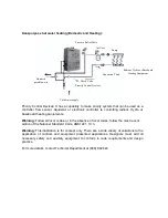
Page 16: ...r other used a means such as a mixing valve shall be installed to temper the water for those uses in order to reduce scald hazard potential Water temperature over 125 F can cause severe burns instantly or death from scalds Chemicals such as diluted Glycol can be used for radiant floor Hydro warm air or Baseboard heating only Basic system drawings and Schematics Heating application only Warning Thi...

Page 17: ...tion of the National Standard Code ANSI Z21 10 3 Warning This illustration is for concept only There are a wide variety of variations to the application of controls and equipment presented applications Designers must add all necessary safety and auxiliary equipment to conform to code requirements and design practice For more details contact Technical Department at 888 882 524 Pressure Relief Valve...

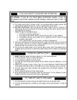
Page 18: ...a qualified service technician to inspect the water heater and to replace any damaged parts WARNING If you do not follow these instructions exactly a fire or explosion may result causing property damage personal injury or loss of life OPERATING INSTRUCTIONS 1 STOP Read the safety information above or in the Owners Manual 2 Turn off all electric power to the water heater 3 Do not attempt to light t...

Page 19: ...ildren or the infirm without supervised DANGER Keep flammable products 1 Far away from heater 2 In approved containers 3 Tightly closed 4 Out of children s reach Vapors 1 Cannot be seen 2 Vapors are heavier than air 3 Go a long way on the floor 4 Can be carried from other rooms to the main burner by air currents DANGER Hot Water Heater temperature over 125 F can cause severe burns instantly or dea...

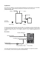
Page 20: ...K2 is 6 9 GPM If it is necessary to achieve higher flow rates for longer periods of time then it can be installed in conjunction with a storage tank A pump will be necessary to keep the water hot We suggest a pump of 1 12 hp or greater depending on the system Recirculation Pressure Relief Valve Hot Water to House Cold Water Inlet Hot Water Return Pump with without Timer Check Valves This system wi...

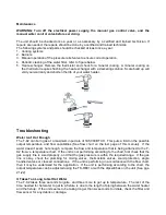
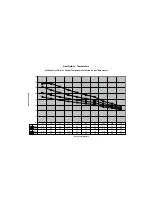
Page 21: ...emperature and flow capabilities See flow chart on the last page of this manual If the water doesn t seem hot enough compare the flow and temperature that is being attained to the T K2 flow vs temperature chart If the unit is not performing according to the chart first check that the gas supply line is sized properly and that the gas pressure is within the required range If the gas line is okay ch...

Page 22: ... self diagnostic for errors If there is a problem with the installation or the unit it will give a signal through a pair of flashing lights on the circuit plate to communicate the source of the problem If the unit has a TK RE01 remote control installed this will give also give a numerical error code Consult the following chart for the meaning of an error code TK RE01 Computer Board TK RE01 Check P...

Page 23: ......

Page 24: ...t allows the maximum output temperature from the T K2 to be adjusted within the range of 95 F to 180 F and it also works as a diagnostic toll that will give a concise error code whenever there is a problem with the unit The temperature options are 95 100 102 104 106 108 109 111 113 115 117 122 131 140 158 167 and 180 F See the troubleshooting section for information on possible error codes TK TV03...

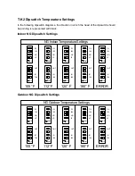
Page 25: ...ON OUT NG LP IN 180 112 105 4 3 2 1 ON 4 3 2 1 ON OUT NG LP IN 180 112 105 4 3 2 1 ON 4 3 2 1 ON OUT NG LP IN 180 112 105 NG Indoor Temperature Settings 105 F 112 F 120 F 180 F ERROR Outdoor NG Dipswitch Settings 4 3 2 1 ON 4 3 2 1 ON OUT NG LP IN 180 112 105 4 3 2 1 ON 4 3 2 1 ON OUT NG LP IN 180 112 105 4 3 2 1 ON 4 3 2 1 ON OUT NG LP IN 180 112 105 4 3 2 1 ON 4 3 2 1 ON OUT NG LP IN 180 112 105...

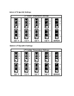
Page 26: ...ON 4 3 2 1 ON OUT NG LP IN 180 112 105 LP Indoor Temperature Settings 105 F 112 F 120 F 180 F ERROR Outdoor LP Dipswitch Settings 4 3 2 1 ON 4 3 2 1 ON OUT NG LP IN 180 112 105 4 3 2 1 ON 4 3 2 1 ON OUT NG LP IN 180 112 105 4 3 2 1 ON 4 3 2 1 ON OUT NG LP IN 180 112 105 4 3 2 1 ON 4 3 2 1 ON OUT NG LP IN 180 112 105 4 3 2 1 ON 4 3 2 1 ON OUT NG LP IN 180 112 105 LP Outdoor Temperature Settings 105...

Page 27: ...Computer board assembly ...

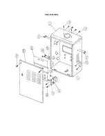
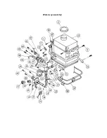
Page 28: ...Case assembly ...

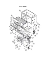
Page 29: ...Burner assembly ...

Page 30: ...Water way assembly ...

Page 31: ...G PLATE 22 O RING 67 GAS INLET 23 GASKET 68 FAN 24 QUICK RELEASE PLATE 69 SCREW 25 QUICK RELEASE PLATE 70 FAN DAMPER 26 SCREW 71 THERMOSTAT 27 FLOW SENSOR 72 SCREW 28 O RING 73 SCREW 29 INLET CONNECTION PIPE 74 PRESSURE SWITCH 30 O RING 75 SILICON TUBE 31 INLET THERMISTOR 76 PRESSURE SWITCH PORTPLATE 32 O RING 77 PRESSURE SWITCH PORT 33 WATER INLET 78 POWER DISTRIBUTION PLATE 34 FREEZE PROTECTION ...

Page 32: ...e 0 0 1 0 2 0 3 0 4 0 5 0 6 0 7 0 8 0 Output Temperature Gallon per Minuite 40 F 4 4 4 1 3 9 3 6 3 4 3 3 3 1 2 7 2 5 2 2 50 F 5 2 4 8 4 4 4 1 3 9 3 6 3 4 3 0 2 7 2 4 60 F 6 2 5 6 5 2 4 8 4 4 4 1 3 9 3 3 3 0 2 6 70 F 6 7 6 7 6 2 5 6 5 2 4 8 4 4 3 6 3 3 2 8 110 115 120 125 130 135 140 155 165 180 ...

Reviews: