background image


- 27 -

INITIAL OPERATION


Check the GAS and WATER CONNECTIONS

 for leaks before firing it for the first time. 

  Open the main gas supply valve to the unit using only your hand to avoid any spark.  

Never use tools. If the knob will not turn by hand, do not try to force it; call a qualified 
service technician. Forced repair may result in a fire or explosion due to gas leaks.   

  Be sure to check next to the bottom of the unit because some gases are heavier than air 

and may settle towards the floor. 


Check the GAS PRESSURE. 

Refer to p. 17.  

  Do not try to light the burner manually. It is equipped with an electronic ignition device 

which automatically lights the burner. 


Check for PROPER VENTING and COMBUSTIBLE AIR

 to the heater. 


Purge the GAS and WATER LINES

 to remove any air pocket.  

  Do not use this water heater if any part has been submersed under water. Immediately call 

a qualified service technician to inspect the water heater and to replace any damaged 
parts.   

CAUTION:  IF YOU SMELL GAS:


  Do not try to start the water heater. 

  Do not touch any electric switch; do not use any phone in your building. 

  Immediately call your gas supplier from a neighbor’s phone. Follow the gas supplier’s 

instructions. 


If you cannot reach your gas supplier, call the fire department.


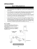
1. 

Once the above checks 
have been completed, 
please clean filter of any 
debris. Refer to p. 31 for 
instructions. 


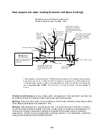
2. 

Fully open the manual 
water control valve on the 
water supply line. 


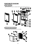
3. 

Open a hot water tap to 
verify that water is flowing 
to that tap.  


Then close the hot water tap. 

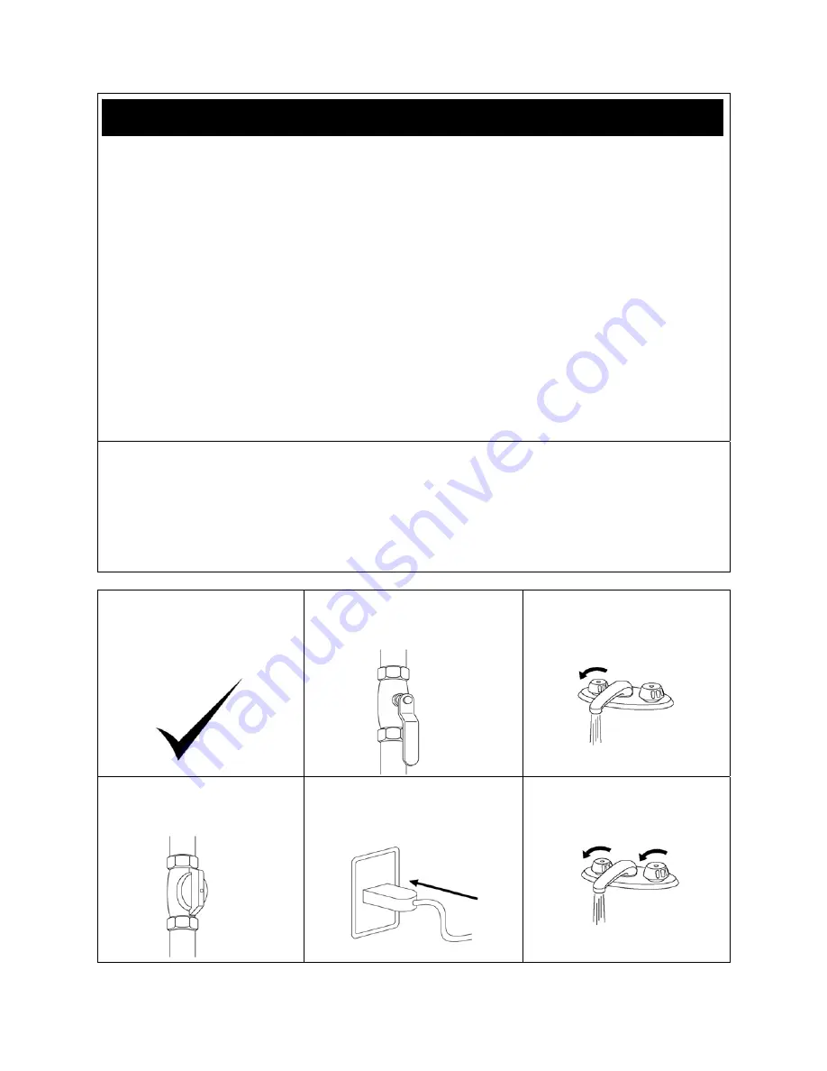
4. 

Fully open the manual 
gas control valve 
installed.  


5. 

Turn on the 120 volt 60 Hz 
power supply to the T-K3/T-
K3-Pro water heater. 


6. 

Now you are ready to 
enjoy hours of endless 
hot water. 


FOR YOUR SAFETY, READ BEFORE OPERATING: 

Summary of Contents for T-K3

Page 1: ...as fitter or a professional service technician Improper installation and or operation or installation by an unqualified person will void the warranty WARNING If the information in this manual is not followed exactly a fire or explosion may result causing property damage personal injury or death TAKAGI Industrial Co USA Inc 5 Whatney Irvine CA 92618 Toll Free 888 882 5244 USA Toll Free 877 877 4953...

Page 2: ... 0 05A Electric Consumption Freeze Protection 111 W 0 93A SPECIFICATIONS INTRODUCTION SAFETY GUIDELINES INSTALLATION General Included Accessories Outdoor Installation Indoor Installation Direct Intake Vent System Venting Instructions Gas Supply Gas Pipe Sizing Water Connections Pressure Relief Valve Electrical Connections Remote Controller Connection Easy Link System Pump Connection Initial Operat...

Page 3: ...and is not accurate to the T K3 T K3 Pro s physical description This manual provides information necessary for the installation operation and maintenance of the Flash T K3 T K3 Pro water heater The model description is listed on the rating plate which is attached to the front cover of the water heater Please read all installation instructions completely before installing this product If you have a...

Page 4: ...E WATER PRESSURE and ELECTRIC RATING If this unit does not match your requirements do not install and consult with Takagi 5 If any problem should occur turn off all hot water taps and turn off the gas Then call a trained technician or the Gas Company or the manufacturer WARNING Water temperatures over 125ºF can cause severe burns instantly or death from scalding The water temperature is set at 122...

Page 5: ...nt to a bedroom or a room that is intended for quiet study or meditation etc Locate your heater close to a drain where water leakage will not do damage to surrounding areas As with any water heating appliance the potential for leakage at some time in the life of the product does exist Takagi will not be responsible for any water damage that may occur If you install a drain pan under the unit ensur...

Page 6: ...Pro to a sealed combustion unit Direct venting allows the T K3 T K3 Pro to draw fresh intake air from the outside The warranty will not cover damage caused to the unit due to installation in a contaminated environment that has not been converted using the TK TV10 5 Particles from flour aerosols and other contaminants may clog the air vent or reduce the functions of the rotating fan and cause impro...

Page 7: ...water can accumulate Do not install this water heater under an overhang less than 3 feet from its top or eaves The area under an overhang must be open to three sides Do not install the water heater vent terminator within 1 ft in the USA of any air intake or building opening and with in 3 ft in Canada of any air intake or building opening Refer to p 14 Do not install next to a dryer or any source o...

Page 8: ...switches above the LED s 4 The outdoor vent cap must be used when unit is installed outdoor Takagi requires the use of its part No TK TV04 5 When installed outdoors the T K3 T K3 Pro water heater shall be wall mounted or mounted on a stand Locate the water heater in an open unroofed area and maintain the following minimum clearances ING Make sure power to the unit is turned OFF before changing the...

Page 9: ...n opening communicating directly with the outside should have a minimum free area of one square inch per 15 000 BTUH input of the total input rating of water heater in the enclosed area When combustion air is supplied from inside the building an opening communicating with the rest of the dwelling should have a minimum free area of one square inch per 1 000 BTUH input of the total input rating of w...

Page 10: ...bstructions If used as a direct vent appliance the T K3 T K3 Pro requires a 3 combustible air supply pipe The intake pipe must be sealed airtight Air supply pipe can be made of ABS PVC galvanized steel corrugated aluminum corrugated stainless steel or Category III stainless steel Change the dipswitch settings to the direct vent system See diagram below Sidewall venting is recommended for the direc...

Page 11: ...stems Inc FasNSeal Flex L Inc Z Flex Inc Z Vent III Metal Fab Inc and Heat Fab Inc Saf T Vent 3 Follow the vent pipe manufacturer s instructions when installing the vent pipe 4 Do not common vent this appliance with any other vented appliance Do not terminate vent into a chimney If the vent must go through the chimney the vent must run all the way through the chimney with Category III approved or ...

Page 12: ...The weight of the vent stack must not rest on the water heater 6 The vent must be easily removable from the top of the water heater for normal service and inspection of the unit 7 The water heater vent must not be connected to any other gas appliance or vent stack 8 Avoid locating the water heater vent terminator near any air intake devices These fans can pick up the exhaust flue products from the...

Page 13: ...nnect any vent from other appliances to the T K3 T K3 Pro vent Use 4 category III approved or Special BH single or double wall stainless steel vent pipe Wall Roof Rain Cap Roof Flashing Sidewall Vent Terminator Vertical Condensation Drain Install according to local codes TK BF01 Backflow Preventor Recommended for freezing weather conditions 36 F and below TK BF01 Backflow preventor Recommended for...

Page 14: ... outside corner G Clearance to inside corner H Clearance to each side of center line extended above meter regulator assembly 3 feet I Clearance to service regulator vent outlet 3 feet J Clearance to non mechanical air supply inlet to building or the combustion air inlet to any other application 3 feet 1 foot 4 feet from below or side opening 1 foot from above opening K Clearance to mechanical air ...

Page 15: ...ide corner if the adjacent wall is less than 2 ft of length the minimum required distance away from the inside corner will be equal to the length of the wall For direct vent sidewall terminations that use two separate penetrations for the intake and exhaust distance the intake and exhaust terminations at least 3 ft away from each other no matter the orientation For multiple unit direct vent sidewa...

Page 16: ...es An exhaust termination must be spaced from a wall or surface in accordance with local codes as well In the absence of such a code an exhaust termination must be a horizontal distance of at least 2 ft away from a wall or surface 2ft Exhaust termination Exhaust and or direct vent sidewall terminations should be at least 2 ft away from an opposite surface wall Do not place the termination directly...

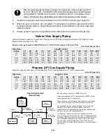
Page 17: ...Ensure that any and all gas regulators used are operating properly and are providing gas pressures within the specified range shown above 4 Until testing of the main gas line supply pressure is completed ensure the gas line to the T K3 T K3 Pro is disconnected to avoid any damage to the water heater MEASURING INLET GAS PRESSURE The T K3 T K3 Pro cannot perform properly without sufficient inlet gas...

Page 18: ...WC supply pressure at a 1 0 WC pressure drop Unit kBTU per Hour Pipe Size Length in Feet inches 10 20 30 40 50 60 70 80 90 100 125 150 200 567 393 315 267 237 217 196 185 173 162 146 132 112 1 1071 732 590 504 448 409 378 346 322 307 275 252 213 1 2205 1496 1212 1039 913 834 771 724 677 630 567 511 440 1 3307 2299 1858 1559 1417 1275 1181 1086 1023 976 866 787 675 2 6221 4331 3465 2992 2646 2394 2...

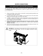
Page 19: ...so recommended on the hot water outlet of the unit If the T K3 T K3 Pro is installed within or subjected to a closed loop water system a thermal expansion tank must be installed 4 Before installing the water heater flush the water line to remove all debris and after installation is complete purge the air from the line Failure to do so may cause damage to the heater 5 There is a wire mesh filter wi...

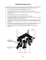
Page 20: ...elief valve needs to be rated for a maximum of 150 psi 6 The discharge piping for the pressure relief valve must be directed so that the hot water cannot splash on anyone or on nearby equipment 7 Attach the discharge tube to the pressure relief valve and run the end of the tube to within 6 from the floor This discharge tube must allow free and complete drainage without any restrictions 8 If the pr...

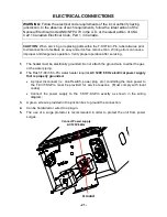
Page 21: ...ration after servicing 1 The heater must be electrically grounded Do not attach the ground wire to either the gas or the water piping 2 The Flash T K3 T K3 Pro water heater requires AC 120V 60 Hz electrical power supply that is properly grounded A proper disconnect i e on off switch power plug etc controlling the main power to the T K3 T K3 Pro must be provided for service reasons Must comply with...

Page 22: ...rminals are firmly fixed 5 Put the remote wires through the hole on the bottom of the unit casing 6 Connect the remote wires to the remote controller terminal properly No polarity Do NOT jump or short circuit wires Computer will be damaged 7 Replace Front Cover securely 8 Wires used for the remote controller connection must be Minimum 18AWG wire No polarity Maximum 400 feet long Back of remote Fro...

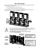
Page 23: ... Easy Link system is limited to 4 units If you connect more than 4 units the first 4 units will work as a part of the Easy Link system but the other additional units will only work as individual units The T K3 T K3 Pro cannot be linked with other different Takagi models in the Easy Link system Gas Hot Cold CAUTION Easy Link connectors are on each unit s computer board To change the dipswitch setti...

Page 24: ...f the T K3 T K3 Pro automatically allocates the unit to each water heater that is part of the Easy Link system Master unit Unit 1 Slave units Unit 2 3 and 4 CAUTION Unless you change dipswitch No 1 of the MASTER unit to ON the system will not work as an Easy Link system The Easy Link system ON LINE lamps will stay unlit and the units will work as individual units MASTER unit SLAVE 1 unit SLAVE 2 u...

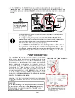
Page 25: ...the SLAVE IN connector of the SLAVE 2 unit the SLAVE 2 unit will work as an individual unit and will not be part of the easy link system WARNING Connecting two MASTER connectors together from two separate units may damage the computer board The communication cable has a female end and a male end so it s impossible to have a MASTER to MASTER connection with the communication cable Do not splice or ...

Page 26: ... RE30 or TM RE10 optional remote controller is not required for the Easy Link system If running the Easy Link system without the TM RE30 or the TM RE10 please make sure the dipswitch settings for the temperature outdoor and direct vent settings on ALL the units are set to the same settings Otherwise the units may not operate properly If the TM RE30 or the TM RE10 is used the temperature on all the...

Page 27: ...ot use this water heater if any part has been submersed under water Immediately call a qualified service technician to inspect the water heater and to replace any damaged parts CAUTION IF YOU SMELL GAS Do not try to start the water heater Do not touch any electric switch do not use any phone in your building Immediately call your gas supplier from a neighbor s phone Follow the gas supplier s instr...

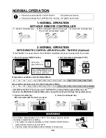
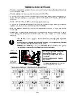
Page 28: ...ot water temperature of the FLASH T K3 T K3 Pro water heater is factory set at 122 F Feel the water temperature before bathing or showering 99 100 102 104 106 108 110 111 113 115 117 122 131 140 158 167 99 100 102 104 106 108 110 111 113 122 131 140 149 158 167 176 185 The temperature and the time will be displayed on the remote controller Temperatures available under the Default Mode 3 Open a hot...

Page 29: ...ackup power supply The freeze protection system will activate when the surrounding and or outside temperatures drop below 36 5 F 2 5 C In any areas subject to freezing temperatures Takagi highly recommends installing the unit indoors In such an installation freezing issues can only occur if cold air enters through the venting into the heat exchanger whether by negative pressures within the install...

Page 30: ... optional temperature remote controller part No TM RE30 With this optional TM RE30 you can set the temperature from 99ºF to 176ºF with various increments Please read the instructions carefully prior to installing the TM RE30 as failure to do so could damage the temperature controller and or the water heater which will void the warranty Turn off the power supply to the heater before changing the di...

Page 31: ...ed any repairs should be done by a licensed technician UNIT DRAINING and FILTER CLEANING 1 Close the manual gas shut off valve 2 Turn off power to the unit and then turn on again 3 Wait 30 seconds and then turn off power to the unit yet again 4 Close the water shut off valve 5 Open all hot water taps in the house When the residual water flow has ceased close all hot water taps 6 Have a bucket or p...

Page 32: ... too high p 28 30 The hot water is not available when a fixture is opened Make sure the unit gets 120V 60Hz power supply If you are using the remote controller is the power button turned on p 28 Is the gas supply valve fully open p 27 Is the water supply valve fully open p 27 Is the filter on cold water inlet clean p 31 Is the hot water fixture sufficiently open to draw at least 0 5 GPM through th...

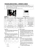
Page 33: ...BLE SOLUTIONS Remote controller does not display anything when the power button is turned on Press the ON OFF button If the lamp lights up This is normal When the unit has not operated for five minutes or more the display turns off to converse energy If the lamp does not light Make sure the unit has power supply Make sure the connection to the unit is correct p 22 An ERROR code is displayed Please...

Page 34: ... 3 digit error code at once Example If your unit has the 321 error code inlet thermistor The 7 Seg LED will flash the 3 digit error code one digit at a time The 7 Seg LED will display 3 2 1 and then repeat the 3 digits The remote controller however will display 321 on its screen in its entirety Easy Link system The 7 Seg LED on the Master unit displays a 5 digit number to signify which unit in the...

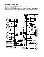
Page 35: ...ater Ground BK BK MV SV3 SV2 SV1 LB G O R O H C F Hi limit switch BL BL BL BL BL BL BL W Y BL O R FM W White R Red BK Black P Purple LB Light blue BL Blue G Green Y Yellow O Orange BR Brown SLAVE IN BK W R BK W R W R R Flow Sensor W Bypass Valve Flame rod Ground AFR rod Y G O Inlet thermistor Output thermistor Mixing thermistor Remote Controller Pump MASTER SLAVE OUT BK W BK W 6 5 4 3 2 1 BK BK BK...

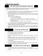
Page 36: ...ce technician Forced or attempted repair may result in a fire of explosion D Do not use this water heater if any part has been under water Immediately call a qualified service technician to inspect the water heater and to replace any damaged parts OPERATING INSTRUCTIONS 1 STOP Read the safety information above or in the Owners Manual 2 Turn off all electric power to the water heater 3 Do not attem...

Page 37: ... The outlet hot water temperature of the T K3 T K3 Pro water heater is factory set at 122 ºF Use this heater at your own risk The set outlet water temperature can cause severe burns instantly or death from scalds Test the water before bathing or showering Do not leave children or an infirm person in the bath unsupervised DANGER Hot Water Heater temperature over 125 ºF can cause severe burns instan...

Page 38: ...mperature over 125 F can cause severe burns instantly or death from scalds Chemicals such as diluted Glycol can be used for radiant floor Hydro fan coil air or Baseboard heating only The diluted solution of glycol must contain LESS than 30 of Glycol Be aware that in closed loop glycol systems low pressure in the heat exchanger can cause low temperature boiling resulting in excessive noise and dama...

Page 39: ...t Comply with Local and State Codes Can Not Be Common Vented with Other Appliances Atmospheric Vacuum Breaker Pump Must Be Sized Properly With Each Application Pump Shall Run 60 Seconds Every 6 Hours Pressure Gauge Apply Correct Thermal Expansion Tank Size Per Application Tempered Water To House Cold Inlet Shut Off Valve Check Valve Will Have 1 8 Hole in Check As Per Mass Code Thermometer Thermost...

Page 40: ...g rain or other weather from entering the unit 4 TK TV10 Direct venting kit This kit can be used convert the T K3 T K3 Pro from a conventional vent system to a direct vent or sealed combustion system This is a CSA tested Takagi conversion kit Install this conversion kit in accordance with Takagi s installation instructions and any applicable codes 5 TK PC01 Pipe cover The TK PC01 Pipe cover protec...

Page 41: ...01 709 710 711 104 7 14 715 716 717 712 001 005 003 051 050 702 051 051 004 052 052 007 052 052 706 707 053 052 054 053 050 006 002 Other than the front cover No 7 all of the T K3 Pro s parts are the same as the T K3 The T K3 and the T K3 Pro share the same components ...

Page 42: ... 40 1 10 7 112 71 6 10 1 114 11 7 1 1 5 106 1 51 15 1 11 6 11 0 151 1 5 1 12 4 11 9 1 18 150 15 6 11 1 10 4 15 7 70 5 1 53 70 3 1 21 15 0 15 0 71 8 70 9 15 0 15 0 10 3 1 5 2 12 0 1 23 1 59 1 54 152 7 0 4 7 20 1 2 2 1 13 1 55 719 154 10 8 05 2 15 0 0 5 4 1 58 7 11 12 5 71 0 ...

Page 43: ...58 401 411 415 410 402 457 452 404 052 418 417 416 453 412 454 458 405 456 408 450 406 450 052 419 455 456 414 458 454 460 407 456 T K3 Pro Heat Exchanger 420 Other than the heat exchanger assembly No 420 all of the T K3 Pro s parts are the same as the T K3 ...

Page 44: ...bly with gas valve assembly NA 401 EKK1X Heat exchanger assembly for T K3 104 EKK25 Fan motor 402 EKK0T Flow adjustment valve Flow sensor 106 EKK0E Flame rod 403 EKK0U Bypass valve 107 EKK0F Igniter rod 404 EKK1U Water inlet 108 EKK1E Gas inlet 405 EKK1V Water outlet 110 EKK1P Damper 406 EKK38 Inlet thermistor 111 EK270 Fan damper 407 EKK2T Output thermistor 112 EKN61 Rod cap 408 EKK1A Mixing ther...

Page 45: ...EH IG Wire 453 EZM15 O ring P15 EPDM 711 EKK10 Gas valve wire 454 EZM14 O ring P14 EPDM 712 EKK36 Pump and multi cable 455 EZM06 O ring P6 EPDM 714 EKK35 RS VG wire 456 EZM04 O ring P4 EPDM 715 EKK33 Water valves wire 457 EM192 Fastener 16A 716 EKK11 Flame rod wire 458 EKK24 Fastener 14 22 717 EKK1Z Thermistors wire 459 EKK39 Fastener 16 25A 718 EKK0B Transformer wire 460 EKH30 Fastener 4 11 719 E...

Page 46: ... F 6 5 5 9 5 4 5 0 4 7 4 3 4 1 3 8 3 6 3 4 3 3 3 0 2 7 2 6 2 5 2 4 2 3 50 F 7 0 7 0 6 5 5 9 5 4 5 0 4 7 4 3 4 1 3 8 3 6 3 3 3 0 2 8 2 7 2 6 2 5 60 F 7 0 7 0 6 5 5 9 5 4 5 0 4 7 4 3 4 1 3 6 3 3 3 1 3 0 2 8 2 7 70 F 7 0 7 0 6 5 5 9 5 4 5 0 4 7 4 1 3 6 3 4 3 3 3 1 3 0 90 95 100 105 110 115 120 125 130 135 140 150 160 165 170 175 180 Output Hot Water GPM When the set temperature is 158ºF or higher max...

Page 47: ...stallation date Takagi Industrial Co USA Inc will furnish a brand new heat exchanger or a refurbished or conditioned tankless water heater with same model For commercial industrial and or recirculation applications heating or domestic and or more than a single family residential dwelling the heat exchanger is covered within three 3 years of usage excluding labor and shipping This does not include ...

Page 48: ... 48 44R018 1 M 001 TK3 TK3PRO 0 ...

Reviews: