background image

- 9 -

Balancing

After the tube assembly has been attached on the mount, the next step is to balance it in 

the R.A. and Dec. axes. If unbalanced, the clamps will not work effectively and the tube 

assembly will abruptly and dangerously turn. When the motor of the mount is rotating, 

unbalancing will cause gearing trouble that will make the life of the mount shorter. When 

balancing, do it with all accessories necessary for observation attached to the tube 

assembly.

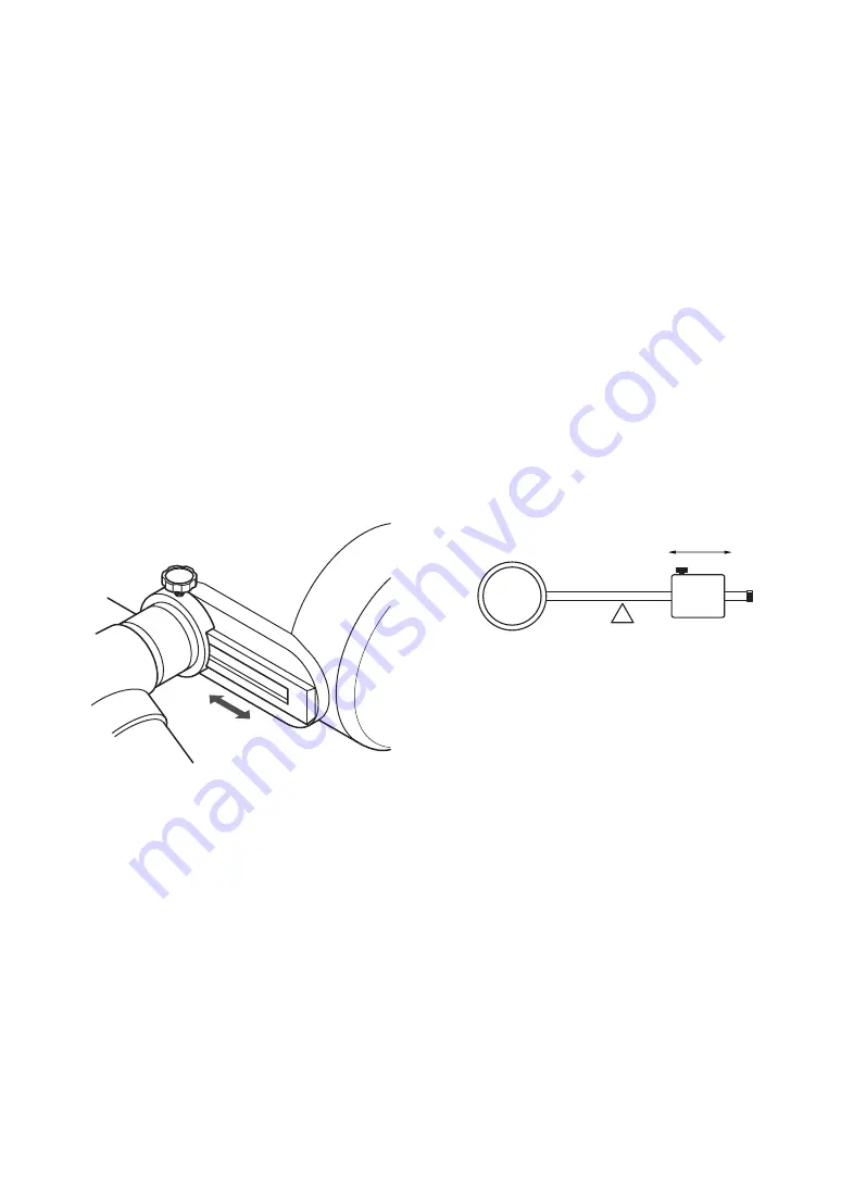
▼Balancing around the Dec. axis


1.  Loosen the Dec. clamp and lock it at 

the position that the Dec. axis becomes 

horizontal.

2.  Loosen  the  handle  of  the  dove-tail 

adapter (F) and move the tube assembly 

forward and backward until it balances. 

In the normal visual observation, place 

the tube assembly at the top of the dove-

tail adapter as illustrated.

▼Balancing around the R.A. axis


1.  When balancing around the Dec. axis 

has  been  made,  lock  the  Dec.  clamp 

firmly.

2.  Loosen the R.A. clamp and see balancing 

around the R.A. axis.

3.  If unbalanced, move the counter-weight 

until it balances and lock the R.A. axis.

4.  If unbalanced at the top of the counter-

weight  shaft,  add  an  extra  weight  to 

balance.

Summary of Contents for Mewlon-180C

Page 1: ...Instruction Manual TAKAHASHI ...

Page 2: ... HR multi layer coating In order to use the telescope to its highest possible capabilities please read this instruction manual very carefully and familiarize yourself with all of the functions that your telescope offers All Takahashi telescopes have been strictly inspected before shipment If there is any trouble with your telescope when unpacked please contact your authorized dealers for proper at...

Page 3: ... assembly on a completely flat surface that totally supports it to protect it from damage Keep the tube assembly out of the sun to prevent the light of the sun going into the tube the reflected sunshine can cause great heat at the focal point and become so intense that it could start a fire When focusing be careful not to pinch your fingers Keep children away from small parts that could be swallow...

Page 4: ...ions for Safe Operation 3 Contents 4 Specifications 5 Tube Assembly Layout 6 Features 7 Setup Procedures 8 Focusing 11 Finder Adjustment 12 Observation 14 Accessories 15 Collimation 18 Care Maintenance 20 System Charts 21 ...

Page 5: ...ving Power 0 64 Limiting Magnitude 13 0 Light Gathering Power 661x When used with Mewlon Flattener Reducer Effective Focal Length 1760 Effective Focal Ratio 1 9 8 Tube Diameter 210mm Total Length of Tube 625mm Total Weight of Tube 6 2kg 13 6lbs Finder Scope 6x30 built in Accessories Dove tail Adapter F Warranty Card Instruction Manual Tools Hex Wrench 1 5mm 2 5mm Note HR High Reflectance ...

Page 6: ... 6 Tube Assembly Layout Main Tube 6x30 Finder Scope Dove Tail Adapter M 50 8 2 Sleeve Coupling S Eyepiece Adapter Cap 31 7 1 Eyepiece Adapter ...

Page 7: ...roduced by a Newtonian reflector This design can produce images visually and by using CCD camera Takahashi has successfully developed a compact and easy to use telescope for planet images of the highest quality The spherical secondary mirror has allowed the mirror making assembling and adjusting of the Dall Kirkham to become easier This has enabled Takahashi to provide high performance on a contin...

Page 8: ...ter F is positioned as illustrated below and lock it firmly Dove Taile Adapter F Clamp Handle Cap Bolt Hex Wrench Tube Holder Base Dec Clamp The finder scope is built in the tube assembly and is designed as the carrying handle When setting the tube assembly on the mount carry it with two hands as illustrated below Dove Taile Adapter F Clamp Handle Tube Holder Base Mount Clamp Handle ...

Page 9: ... around the Dec axis 1 Loosen the Dec clamp and lock it at the position that the Dec axis becomes horizontal 2 Loosen the handle of the dove tail adapter F and move the tube assembly forward and backward until it balances In the normal visual observation place the tube assembly at the top of the dove tail adapter as illustrated Balancing around the R A axis 1 When balancing around the Dec axis has...

Page 10: ...ast less expensive with high performance Available in 31 7mm 1 barrel Abbe 4mm Abbe 6mm Abbe 9mm Abbe 12 5mm Abbe 18mm Abbe 25mm Abbe 32mm Attaching Accessories Adapters and rings are attached to the visual back in order to use various accessories Please check the system charts and attach the desired accessories correctly Standard connection is as below Erfle With 3 group 5 element optics offering...

Page 11: ...e is moved inward After an eyepiece has been attached on your telescope precise focusing is needed to observe objects and landscapes clearly If not correctly focused your telescope cannot display its capabilities Precise focusing is absolutely necessary especially in astro imaging Always use the best possible focus with the following procedures Caution The optical axis of the Mewlon 180C could bec...

Page 12: ...e following procedure 12 Finder Adjusting Screw Lock Ring Focus Lock Ring Eyepiece Finder Field of View of the Finder Field of View of the Main Telescope Collimating the Optical Axis The finder scope has been collimated at the factory before shipment Therefore usually the collimation is not needed when you purchase your telescope However if the collimation should be lost by some reason you can adj...

Page 13: ... object precisely at the crosshair If the object shifts as illustrated loosen screw A and tighten B C screws to move the object on the crosshair When the object is positioned on the crosshair tighten the adjusting screws firmly 8 Finally tighten the lock ring firmly and lock the visual back Please understand the relationship between the movements of the three adjusting screws and the movement of t...

Page 14: ...her details of these parts please refer to the next page Astro Imaging Magnified Imaging When imaging the craters of the Moon and planets magnified imaging can be done with the parts optionally available When imaging the Moon s surface you can enjoy a wide variation of imaging because the Moon has ample illumination In the case of planetary imaging magnify it as large as possible according to seei...

Page 15: ...e Holder 31 7D The 4 Turret Eyepiece Holder 31 7D is a convenient accessory that allows the observer to use 4 eyepieces with different magnifications and it is easily changed by turning the turret This turret accepts 4 different eyepieces and allows eyepieces to be changed quickly by turning it In addition this device has a built in 90 degree prism that allows to observer view the entire sky conve...

Page 16: ...cus Ring is necessary Basically the Prime Focus Ring M43 M42 and the T Mount DX S are used Mount DX DX S In order to attach a DSLR camera the T Mount DX WR is used for the prime focus imaging with the Prime Focus Ring 50 8 φ 50 8 M54 and by the Flattener Reducer and the T Mount DX S for magnifying imaging by the TCA 4 and the prime focus imaging with the Prime Focus Ring M43 M42 The T Mounts are a...

Page 17: ...is not suited for deep sky imaging at prime focus However you can enjoy deep sky imaging using the Mewlon f 9 8 Flattener Reducer which decreases the focal ratio to f 9 8 and reduces coma Focal Length 1760mm Focal Ratio f 9 8 T mount DX WR Mewlon Flattener Reducer DSLR Camera ...

Page 18: ... The scope should be collimated after about an hour to allow the optics to equalize with the outside temperature 1 Remove the spider cover by turning it as arrowed then the adjusting screws are exposed Be careful not to drop the cap into the tube when removing the threaded cover 2 Select a star brighter mag 2 3 and higher in the sky and center it at the field of view Focus it by turning the focusi...

Page 19: ...ment is done and make sure all the screws being correctly tightened thus keeping the secondary mirror attached firmly in place Sometimes a collimation star image can move out of field of view when the screws are moved When a star image goes out of the center during the alignment procedure continue the alignment by replacing the star image with another at the center View Field Loosen this screw Loo...

Page 20: ...ck on to the mirror set it precisely in place with the cell Then the optical axis will be hardly out of order Remove the three screws in the places shown 1 Place the tube assembly on its front on a level surface 2 Holding the visual back stand the tube assembly on its front take out the cell cap and remove the three screws holding the primary mirror cell 3 Pull up the primary mirror cell slowly wi...

Page 21: ...TKA00404 4 Turret Eyepiece Holder 31 7D 30 TKA00206 Prime Focus Ring M43 M42 32 TKA01250 T Mount DX S EOS TKA01254 T Mount DX S Nikon 33 TKA01251 T Mount DX WR EOS TKA01255 T Mount DX WR Nikon 34 DSLR Camera 35 TKA00207 Prime Focus Ring 50 8 2 φ 50 8 M54 36 TKA00210 TCA 4 47 31 7 1 Eyepiece 48 50 8 2 Eyepiece 49 TKA00547 Diagonal Prism 31 7 1 MC 74 TKA00543 Diagonal Mirror 50 8 2 75 TKA00111 Adapt...

Page 22: ... 22 MEMO Version 1 00 ...

Page 23: ... 23 ...

Page 24: ...TAKAHASHI SEISAKUSHO Ltd 41 7 Oharacho Itabashiku Tokyo 174 0061 JAPAN PHONE 81 3 3966 9491 FAX 81 3 3966 9524 ...

Reviews: