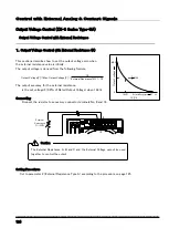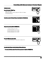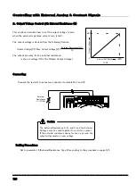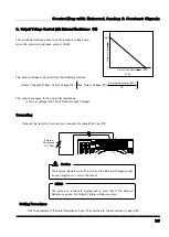
Using in Series/Parallel Operation
------------------------------------------------------------------------------------
114
SERIAL I/F 1
SERIAL I/F 2
TERMINATION
LINE INPUT
OFF
ON
IN
OUT
M/S CONTROL
SENSE
+
DC OUTPUT
-
+ -
SERIAL I/F 1
SERIAL I/F 2
TERMINATION
OFF
ON
IN
OUT
M/S CONTROL
SENSE
+
DC OUTPUT
-
+ -
100-240~,50/60Hz,7A MAX
LINE INPUT
負 荷
-
+
Series Operation
A series connection of two ZX power supply outputs can be used to double the output voltage. Further, Master-
Slave Series Operation, the controlling of the output with a single Master, is available.
Connecting
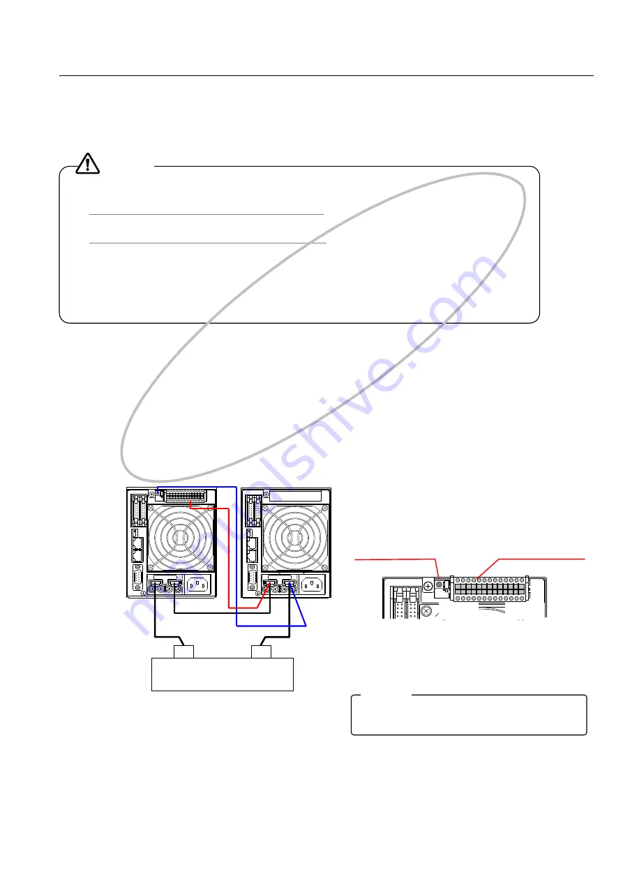
Connect as shown in the below diagram.
◆Load Wire Connection
① Connect wires from the Slave’s minus terminal to the Master’s plus terminal.
② Connect wires from the Slave’s plus terminal to the Load’s plus terminal.
③ Connect wires from the Master’s minus terminal to the Load’s minus terminal.
◆Control Terminal Wiring
① Connect wires from the Slave’s external control connector No. 22 terminal to the Master’s plus terminal.
② Connect wires from the Series control connector to the Master’s minus terminal.
Operation
1.Setting Slave Unit
① Press the Function “FUNC.” key.
② Select Item 73 with VOLTAGE dial.
③ Change the set value to 1 (Slave Mode) with CURRENT dial.
④ Press the FUNC. key again to finalize settings.
●
An LA type is necessary for the Slave unit. (Both the L and LA types can be used for the Master Unit.).
●
Series operation is only possible with models that have the same number indicated in the xxx part of ZX-S-xxx.
●
Connecting different device models will result in breakdown.
●
Turn all series connected ZX-S Series input power (POWER switch) ON.
●
Please calibrate the output voltage for the Slave before use.
●
FUNCTION Settings items, when operating in Slave, are restricted.
●
When operating in Slave, the only valid keys during an alarm reset are the OVP + OCP (pushed simultaneously),
"OCP", "FUNC.", and "LOCAL" keys.
●
The indication on the front display during series operation shows the outputs of the Master unit and the Slave
unit respectively. (When the output voltage is 160V, both the Master unit and the Slave unit will be 80.00V.
Caution
(Master Unit)
(Slave Unit)
IN
OUT
1
13
26
14
外部コントロール用
コネクタ(付属)
直列コントロール用
コネクタ
When returning to Master, set FUNCTION Item 73 to 0,
Item 51 to 0, and Item 60 to 1.
MEMO
Load
Series Control
Connector
External Control
Connector (Accessory)
This feat
ure is not
applicable
to H t
ype.
Summary of Contents for ZX-S-H Series
Page 1: ...Constant Voltage Constant Current DC Power Supply series Instruction Manual ...
Page 37: ...Basic Operations 33 This is blank page ...
Page 59: ...Useful Function 55 This is blank page ...
Page 115: ...Using via Digital Data Communication 111 This is blank page ...
Page 141: ...Controlling with External Analog Contact Signals 137 This is blank page ...
Page 147: ...Special Loads 143 This is blank page 守 ...
Page 188: ... 184 付録 External Diagrams ZX S 400H 400HA 4 M3 ...
Page 189: ...Appendix 185 ZX S 800H 800HA ...
Page 190: ...Appendix 186 ZX S 1600H 1600HA ...


