background image


4

 / 

17


5.  Specifications 


6.  Camera    I / O 


6-1    Power connector


Number of pixels

1024

Unit cell size

10

μ

m×10

μ

m

Photo array length

10.24 mm

Data rate

50 MHz

Scan rate (scan/sec)

45.45 kHz Max.

Line transfer pulse input

22 

μ

sec

Video output (Digital output)

Base Configuration

2×8/10 bit

Sensitivity

50 V/lx.sec

Saturated exposure amount

1.3 lx.sec

Output ununiformity

 3%  standard

at 50% of saturation output(on the element)

Power supply

+12V ±0.5V (400mA)

Operational
ambient temperature

0 ~ +40℃

(Shall be free from dew condensation and frost.)

Operational
humidity range

85% MAX

Storage temperature range

-10℃ ~ +65℃

Weight

360g or less

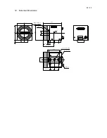
External dimension (mm)

64(W)×64(H)×80.3(D)

lens mount

            Nicon F mount(standard)
            Asahi K mount(optional)

Pin No. Signal name Pin No. Signal name

1

+12V

4

GND

2

+12V

5

GND

3

+12V

6

GND

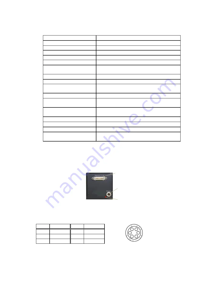
Connector panel 

Camera Link connector 

Power connector   

Power indicator 

Power connector pin assignment 

6

5

4

3

2

1

Power connector (HR10A-7P-6S    HIROSE) 
(Pin  arrangement  viewed  from  the  outside  of 
the camera)


Summary of Contents for tl-1024ucl

Page 1: ...Otsu Shiga 520 2144 JAPAN TEL 81 77 545 4331 FAX 81 77 545 4335 Image Inspection Dept 86 66 Nomizo cho Otsuka Yamashina ku 607 8135 Kyoto JAPAN TEL 81 75 593 9300 FAX 81 75 593 9790 T o k y o O f f i...

Page 2: ...Specifications 4 6 Camera I O 4 6 1 Connector pin assignment of the Power connector 6 2 Connector pin assignment of the Camera Link connector 7 Timing chart 6 8 Serial communication protocol 7 9 Expos...

Page 3: ...incorporated 3 Applications Image processing device for Image inspection Foreign substance detector on high speed production line Surface inspection apparatus of sheet like object Pinhole detector 4 C...

Page 4: ...turation output on the element Power supply 12V 0 5V 400mA Operational ambient temperature 0 40 Shall be free from dew condensation and frost Operational humidity range 85 Storage temperature range 10...

Page 5: ...f Base Configuration 8 Bit 10Bit 1 26 14 13 Camera Link connector pin out Port bit 10 bit x 4 Port bit 10 bit x 4 Port A0 A0 Port B4 B8 Port A1 A1 Port B5 B9 Port A2 A2 Port B6 nc Port A3 A3 Port B7 n...

Page 6: ...INE VALID PIXEL DATA PORT A OS1 Dummy Signal 16pixels 1 Line Output Period 555 CLOCK TL 1024UCL Timing Chart S101 7 S101 5 D6 59 clock D16 D20 D18 D 28 D 26 D22 8CLOCK D24 PIXEL DATA PORT B OS2 D1 D7...

Page 7: ...sync 2 n expt exposure time a 12 8 sec TL 5150UCL 10 24 sec 3 Exposure control system switching Refer to the time chart on P 11 Line period exposure Exposure during periodic time Fixed time exposure...

Page 8: ...AIN position X arbitrary numeral indicating channel Gain position GAIN position of the camera Channel Channel to specify the GAIN control device for each CCD output line EEPROM EEPROM incorporated in...

Page 9: ...r e g Input error Input value is beyond the setting range Input gainpos 96 Output NE e g Input error Input value is beyond the setting range Input ch1gain1 2000 Output NE NC is returned when in inputt...

Page 10: ...1 12 Exposure control set expc N CR 0 Line period exposure 1 Fixed time exposure 2 Pulse width exposure OK Set the exposure control state of the camera Settable only at ctrl 1 Exposure time 13 Exposu...

Page 11: ...T 0 DATA output duration ST OUT 0 ST 3 DATA output duration ST OUT 2 Exposure time Exposure time Pulse width exposure expc 2 Exposure during the period of the pulse width H of EXT SYNC CC1 Minimum exp...

Page 12: ...Communications Hyper Terminal 2 The windows will appear with the picture below 3 When the next picture appears enter any name e g GMA_RS232C Then click the OK button 4 When the next picture appears se...

Page 13: ...ct each items as follows 9600 8 None 1 Non Then click the OK button Communication settings Baud Rate 9600bps Data Length 8bit Start Bit 1bit Stop Bit 1bit Parity Non Xon Xoff Control Non 6 The next pi...

Page 14: ...ngs tag 9 When the next picture appears click the ASCII Setup button 10 When the next picture appears select each items as follows 0 0 blank blank Then click the OK button 11 The screen display will r...

Page 15: ...send it out If OK is displayed on the screen communication processing has been completed 13 Select Start Programs Accessories Communications Hyper Terminal 1 when to launch the Hyper terminal again wi...

Page 16: ...t with a voltage within the range of specifications and do not connect the equipment to a power source that contains intense noise components In such case the image output from the camera may contains...

Page 17: ...17 17 12 External dimensions Element 6 18 8 0 3 63 5 63 5 8 3 1 3 1 7 5 17 5 6 45 4 18 F B 4 6 5 F Mo unt Camera Link Depth Depth 51 50 20 2 64 3 M2 6 Depth 6 Four faces...

Reviews: