


Assembly instructions
Assembly
24 / 35
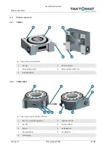
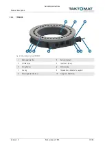
Rotary indexer TMF
Version 1.0
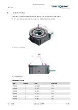
5.3
Installation
DANGER
Electric shock
Touching live parts poses an immediate danger to life
•
Work on electrical systems may only be carried out by qualified electricians
•
Before starting work, disconnect the system, secure it against being switched on again and
make sure that no voltage is present
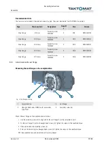
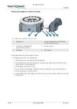
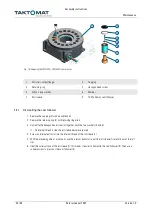
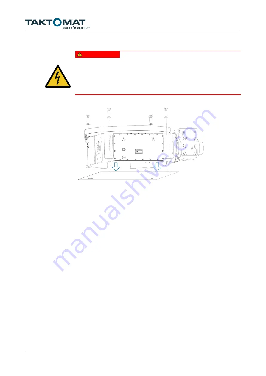
Fig. 14: Rotary indexer installation
The mounting surface must be level.
1. Clean the mounting surface and apply an oil film.
2. Place the rotary indexer on the mounting surface.
3. Fix the rotary indexer with screws and alignment pins according to the requirements.
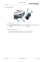
4. Compare the supply voltage with the data on the nameplate.
5. Connect the drive unit.
6. Earth the housing of the rotary indexer with an adequate cross-section.
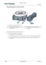
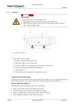
Setting the zero point using the vernier
The vernier is used to set the zero point. The vernier can be used to always set the roll star / output flange to the factory zero
position of the rotary indexer. This is necessary for applications that have a zero position or a reference point.
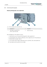
Roll star / output flange attachments
Note the following regarding attachments on the roll star / output flange:
•
Maximum weight moved (according to TAKTOMAT project planning).
•
Minimum time until positioning (according to TAKTOMAT project planning).
•
Maximum overhang (tipping moment) (according to TAKTOMAT project planning).
•
Do not exceed the max. tightening torque of the mounting screws.


