


Assembly instructions
Operation
Version 1.0
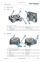
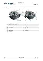
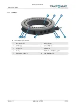
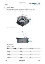
Rotary indexer TMF
25 / 35
6
Operation
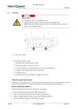
NOTICE
Improper activation can cause material damage
•
Inching mode is not permitted without a suitable universal controller (TIC)
•
Use a suitable universal controller (TIC)
General requirements for operation
Operation of the rotary indexer is only permitted in a complete, CE-compliant machine or system.
The rotary indexer may not be operated with defective or disabled safety devices.
6.1
Operating modes
WARNING
Moving components
Moving components can cause serious injuries
•
During operation, do not reach into moving components or work on moving components
•
Do not dismantle or bypass protective covers
The rotary indexer is designed for different operating modes. These operating modes must be implemented by means of an
external controller.
Normal operation
In normal operation, the roll star / output flange moves in one direction from one position to the next. The rotational direction
of the roll star / output flange corresponds to the rotational direction of the drive. The rotational direction of a three-phase
a.c. motor can be reversed by swapping two phases of the supply voltage.
Reversing operation (reciprocating operation)
In this mode the roll star / output flange oscillates (shuttles) continuously, back and forth between two positions. The drive
of the partly completed machinery is reversed in the respective latching phase.
Inching mode
In inching mode, the roll star / output flange moves in small increments between two latching positions.
The cylinder is unable to accelerate and decelerate the accumulated load gently. As a result, high accelerations occur, which
impact the mechanics. Inching may only be carried out with a suitable universal controller. A suitable controller is, for
example, the TIC controller (TAKTOMAT Indexing Controller).
Emergency stop
The emergency stop stops the movement of the roll star / output flange immediately. The resultant load that is built up
impacts the mechanics. The emergency stop should therefore only be used in emergency situations.


