background image


4. 

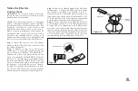
Step  3.

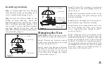
  Pass  the  120-volt  supply  wires  through 

the  center  hole  in  the  ceiling  hanger  bracket  as 
shown in Fig. 8)

Step  4.

 Secure the hanger bracket to the ceiling 

outlet box with the screws and washers provided 
with your outlet box.

Step  5

.Remove  the  hanger  pin,  lock  pin  and  set 

screws from the top of the motor assembly.

Step  6.

  Route  wires  exiting  from  the  top  of  the 

fan  motor  through  the  collar  cover,  canopy 
cover,    canopy  and  then  through  the  ball  / 
downrod. (Fig. 8A)

Step  7.

  Align  the  holes  at  the  bottom  of  the 

downrod with the holes in the collar on top of the 
motor  housing  (Fig.8A).  Carefully  insert  the 
hanger  pin  through  the  holes  in  the  collar  and 
downrod.    Be  careful  not  to  jam  the  pin  against 
the wiring inside the downrod. Insert the locking 
pin  through  the  hole  near  the  end  of  the  hanger 
pin  until  it  snaps  into  its  locked  position,  as 
noted in the circle inset of Fig. 8A.

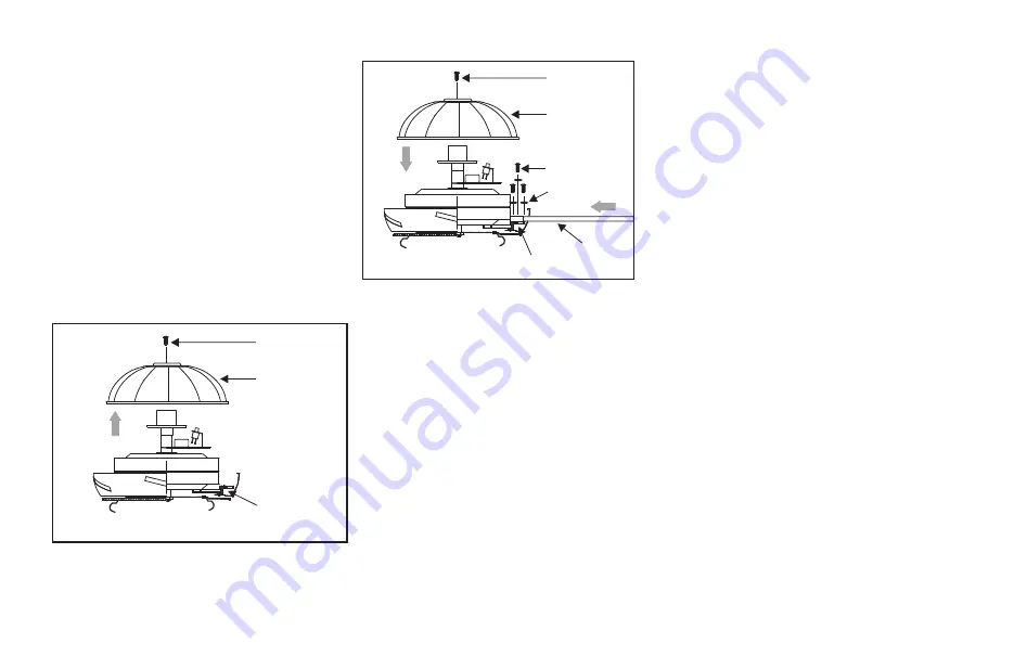
Installing the blade 

Step  1

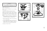
.  Disassemble  the  top  housing 

from  the  motor  body  by  loosening  the  6 
screws from the top housing.(Fig. 5)

Step  2

.Locate  the  blade  bracket  in  the 

bottom  of  motor  housing,    insert  the 
blade through the slot  in housing.  Align 
holes  in  blade  and  blade  bracket    and 
secure  with  3  screws  and  fiber  washers 
provided.  Repeat  the  process  with  the 
other blades. Reinstall the top housing to 
the motor body. (Fig. 6)

Figure 5

Top housing

Screws

Blade bracket

Figure 6

Top housing

Screws

Blades screws

Blades

Blade bracket

Fiber washers

Hanging the Fan

REMEMBER


to turn off the power. Follow 

the steps below to hang your fan properly:

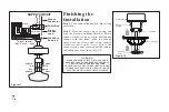
Step  1.

  Remove  the  decorative  canopy 

bottom  cover  from  the  canopy  by  turning 
the cover clockwise.(Fig. 7)

Step  2.   

Remove  the  hanger  bracket  from 

the canopy by loosening the two screws on 
the bottom of the canopy in 1/4" from the 
screw  head  and  turning  the  canopy 
counter clockwise.(Fig, 7)

Summary of Contents for Renaissance

Page 1: ...7 feet clearance from the trailing edge of the blades to the floor 7 Do not operate reversing switch while fan blades are in motion Fan must be turned off and blades stopped before reversing blade di...

Page 2: ...Fluorescent lamp 8 Glass shade 9 Glass holder 10 Balancing kit 11 Receiver 8 wire nuts 12 Transmitter holder 2 mounting screws 13 Loose parts bag containing a Blade attachment hardware 16 screws 16 f...

Page 3: ...let box and its support must be able to fully support the moving weight of the fan at least 50 lbs Do not use plastic outlet boxes Figures 1 2 and 3 are examples of different ways to mount the outlet...

Page 4: ...ntil it snaps into its locked position as noted in the circle inset of Fig 8A Installing the blade Step 1 Disassemble the top housing from the motor body by loosening the 6 screws from the top housing...

Page 5: ...ng the set screw at the top of the downrod which holds the hanger ball to the downrod 2 Slide the hanger ball down the downrod and remove the support pin 3 Insert the support pin in the holes at the t...

Page 6: ...the receiver Connect the blue wire from the fan to the blue wire marked FOR LIGHT from the receiver Connect the purple wire from the fan to the purple wire from the receiver Connect the gray wire fro...

Page 7: ...s necessary until the canopy and canopy cover are snug Fig 12 WARNING MAKE SURE TAB AT BOTTOM OF HANGER BRACKET IS HANGER PROPERLY SEATED IN GROOVE OF HANGER BALL BEFORE ATTACHING CANOPY TO BRACKET FA...

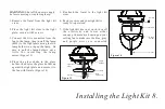
Page 8: ...l e f o r i n s t a l l i n g t h e l a m p easier Figure 13 4 Place the glass shade in the glass holder then raise the glass holder up against the light plate and secure it to the fan with finials F...

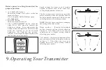
Page 9: ...r depend on factors such as the room size ceiling height number of fans etc The Reverse switch is located on top of the motor assembly Slide the switch to the Left for warm weather operation Slide the...

Page 10: ...Do not use water when cleaning This could damage the motor or the wood or possibly cause an electrical shock 3 You can apply a light coat of furniture polish to the wood blades for additional protect...

Page 11: ...ub is tight 3 Make sure wire nut connections are not rubbing against each other or the interior wall of the switch housing CAUTION Make sure main power is off 4 Allow a 24 hour breaking in period Most...

Reviews: