background image

3  MECHANICAL INSTALLATION

3.1  SELECTING THE LOCATION

·  The modules are certified according to the norm IEC 61215 and others for safe operation in moderate climates.
·  Do not expose the modules to chemicals.
·  Do not place the modules in standing water. The junction box is splash-proof only.
·  Do not install the modules near flammable gases and vapors (e.g. gas containers) or near open  

flames and flammable materials. Solar modules are not explosion-proof operating equipment. 

·  If there is exposure to salt (i.e., marine environments) and sulfur (i.e., sulfur sources, volcanoes),  

there is a risk of corrosion.

·  A module is considered shade-free when it is entirely unshaded throughout the year  

(e.g. by buildings, chimneys, trees). Even partial shading of the modules (e.g. by overhead lines,  
dirt, snow) should be avoided.

3.2  SELECTING THE PROPER SUPPORT FRAME

Always observe the instructions and safety precautions included with the support  
frames to be used with the modules. Install each module to a mounting structure:
·  That is made of durable, corrosion-resistant and UV-resistant material.
·  That can transfer forces on the module to the assembly substructure.
·  That ensures that no mechanical stress (e.g. caused by vibrations, twisting  

or expansion) is generated on the module.

·  That ensures sufficient back ventilation of the module.
·  That ensures long term stability.
·  That will not give rise to galvanic corrosion in case of direct metal contact  

(i.e. grounding lead, screws, washers, etc.)

·  That allows for strain-free expansion and contraction due to natural ambient temperature variations.

3.3   MOUNTING

Modules connected in series should be installed at the same orientation and angle. Different orientations or angles 
may cause a loss of power output due to the change in sunlight exposure. 
·  When developing the final layout of photovoltaic system, consider keeping suitable access to allow the main-

tenance and inspection works. To minimize risk in the event of an indirect lightning strike, avoid forming loops 
when designing the system.

·  The modules may be installed in landscape or portrait format.
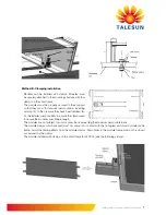
·  Install the module in such a way that the junction box is positioned 

in the upper area of the module and the wires hang downwards.

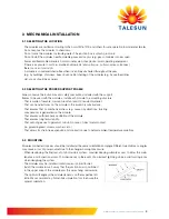
·  The optimal tilt angle of the module depends on the respective lati-

tude. We recommend a photovoltaic simulation tool to ensure the 
optimal orientation.

Installation manual for crystalline solar photovoltaic modules     

5

Summary of Contents for TP672M-315

Page 1: ...electing the proper supporting frame 5 3 3 Frame holes mounting 5 4 Electrical mounting 4 1 Module selection 9 4 2 Safety factor 9 4 3 General installation 9 4 4 Grounding 10 5 Commission and maintena...

Page 2: ...allation Information for operators Keep these instructions safe for the entire useful life of the solar installation Please contact your plant supplier for information concerning the formal requiremen...

Page 3: ...can cause arching resulting in grave or mortal injury The severity increases when several modules are connected in series Cover the solar modules with opaque material for the entire duration of assem...

Page 4: ...eners on the modules Use only insulated tools that are approved for work on electrical installations Do not use light concentrators e g mirrors or lenses to attempt to increase the capacity of the mod...

Page 5: ...the assembly substructure That ensures that no mechanical stress e g caused by vibrations twisting or expansion is generated on the module That ensures sufficient back ventilation of the module That...

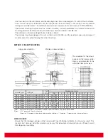
Page 6: ...le support structures used to support PV modules at correct tilt angles should be wind and snow load rated by appropriate local and civil codes prior to installation Pole mount When installing a modul...

Page 7: ...ponsibility to ensure the clampsused to secure the module sare strong enough The modules are not subject to wind or snow loads exceeding the maximum permissible loads The module clamps which are used...

Page 8: ...edge to 1 4 width of the short frame Use a torque wrench for installation and the compression for each clamps is not strong to avoid potential damages to module frames The recommended maximum compres...

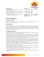
Page 9: ...of the modules and all other system components If modules are connected in series the total voltage is equal to the sum of individual voltages The recom mended max number of module N Vmax system Voc...

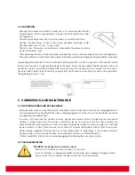
Page 10: ...tion The tightening torque is 1 Nm 5 COMMISSION AND MAINTENANCE 5 1 Blocking diodes and bypass diode Blocking diodes prevent current flowing from the battery to the module when no electricity is being...

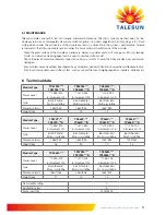
Page 11: ...Technical data Module Type TP672M TP672M B TP660M TP660M B TP654M TP654M B Power Level 265 315 in increment of 5 215 265 in increment of 5 195 235 in increment of 5 Type 6inch 72cells Multi crystalli...

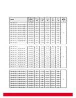
Page 12: ...255B 1000 IEC 255 30 2 8 44 37 5 8 81 TP660M 250 TP660M 250B 1000 IEC 250 30 1 8 31 37 3 8 78 TP660M 245 TP660M 245B 1000 IEC 245 30 0 8 17 37 2 8 69 TP660M 240 TP660M 240B 1000 IEC 240 29 8 8 06 37...

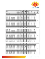
Page 13: ...IEC 250 30 3 8 25 37 3 8 69 TP660P 245 TP660P 245B 1000 IEC 245 30 1 8 14 37 1 8 65 TP660P 240 TP660P 240B 1000 IEC 240 29 7 8 08 36 9 8 62 TP660P 235 TP660P 235B 1000 IEC 235 29 5 7 97 36 8 8 59 TP66...

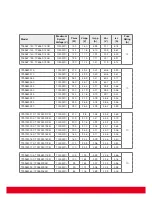
Page 14: ...240 47 2 5 09 58 8 5 48 TP596M 235 1000 IEC 235 46 8 5 02 58 6 5 46 TP596M 230 1000 IEC 230 46 5 4 95 58 2 5 39 TP572M 210 TP572M 210B 1000 IEC 210 38 5 53 45 8 5 83 10 TP572M 205 TP572M 205B 1000 IE...

Page 15: ...sales eu talesun com Web www talesun eu com USA Talesun Solar USA 111W Saint John Street Suite 900 San Jose CA 95113 USA Tel 1 800 276 0823 Fax 1 408 645 7111 E Mail sales USA talesun com Web www tal...

Page 16: ...www talesun eu com...
Reviews: