KB-ML-5 & KB-ML-10 Instructions
Copyright 2009 Talk-A-Phone Co. All rights reserved.
Talk-A-Phone
Co.
• 7530 North Natchez Avenue • Niles, Illinois 60714-3804
Rev. 7/28/09
Phone 773.539.1100 • Fax 773.539.1241 • info@talkaphone.com • www.talkaphone.com
All prices and specifications are subject to change without notice.
Talk-A-Phone, Talk-A-Lert, Scream Alert and WEBS are registered trademarks of Talk-A-Phone Co.
INSTALLATION
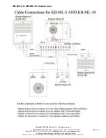
Place each station in the desired location. Run a separate length of TALK-A-PHONE #6303 (3-conductor
shielded) cable from each Sub-Station to the Master. With #6303 shielded cable, connect bare wire of
#6303 to terminal “R” on the Master and to terminal “3” on Sub. NOTE that wire from terminal “2” on each
Sub-Station connects to terminal number of the Sub-Station in the system. Note also that lead wires (of
matching colors to TALK-A-PHONE cable) extend from rear of model K-LR-3W, and are used for
connection. Models K-LR-3 and K-LR-3M have terminal strips.
Underneath the Master and Sub-Station is a cable clamp. Remove screw on cable clamp and pass
interconnecting cable underneath clamp. Adjust cable clamp so that it holds cable securely, and replace
screw.
The Master Station is powered by a separate power supply (included), which connects to the “+” and “-“
terminals on the terminal strip on the bottom of the unit. The black wire on the power supply connects to
the “-“ (minus) terminal, and the black with white stripe wire connects to the “+” (plus) terminal. Your
installation will require grounding of the unit itself. You can connect a ground wire from the “G” terminal
on that terminal strip to the screw on the metal cover plate of the power outlet. That screw is usually
earth ground. The power supply cord should be routed through the strain relief on the bottom of the
chassis.
Care should be taken that no part of the cable is too near electric or telephone wiring, etc., nor should it
be shorted to any grounded conductors, radiators, pipes, beams, etc., and the bare wire at the various
terminals should not short from one terminal to the other nor the metal chassis. When staples are used to
hold the cable in place, use only insulated staples and do not drive them in so hard as to cause the wires
inside the cable to short to each other.
CONTROLS
VOLUME CONTROL:
Located at the left of the cabinet on the Master Station only. Rotate clockwise to
increase volume.
STATION SELECTOR SWITCHES:
Located across front of the cabinet on the Master Station only. To
select Sub-Station corresponding to number above switch, push "in" with slight pressure. More than one
switch can be depressed at the same time. Return switches to “off” position by pushing again.
TALK-LISTEN CONTROL:
Located on the right of the cabinet, (left on the K-LR-3W). Basically, push in
to “talk”; release to “listen”. (also see “private” and “non-private” operation of Sub-Stations in these
instructions.)
PERFORMANCE CONTROL:
Located underneath Master Station, directly adjacent to front bumper foot.
Performance Control is locked into position by a locking bar. The Performance Control provides for
optional “private”-”non-private” operation of the Sub-Stations and is placed in one of two positions. When
control is placed in position towards the rear of unit, all Sub-Stations will function “non-privately”. System
is shipped from factory with Performance Control in “non-private” position and can be placed in “private”
position at any time. To change position of Performance Control, 1) Unscrew bumper foot alongside
Performance Control. 2) Remove locking bar. 3) Place Performance Control in the desired position. 4)
Place opening on one end of locking bar over Performance Control (Performance Control should protrude
through locking bar opening). Place opening on opposite end of locking bar over opening on chassis into
which the bumper foot fastens. 5) Screw bumper foot back into place. NOTE: Also see “private”-”non-
private” operation of Sub-Stations in these instructions.


