


Tally Dascom DT-210/230 User Guide V1.3
71
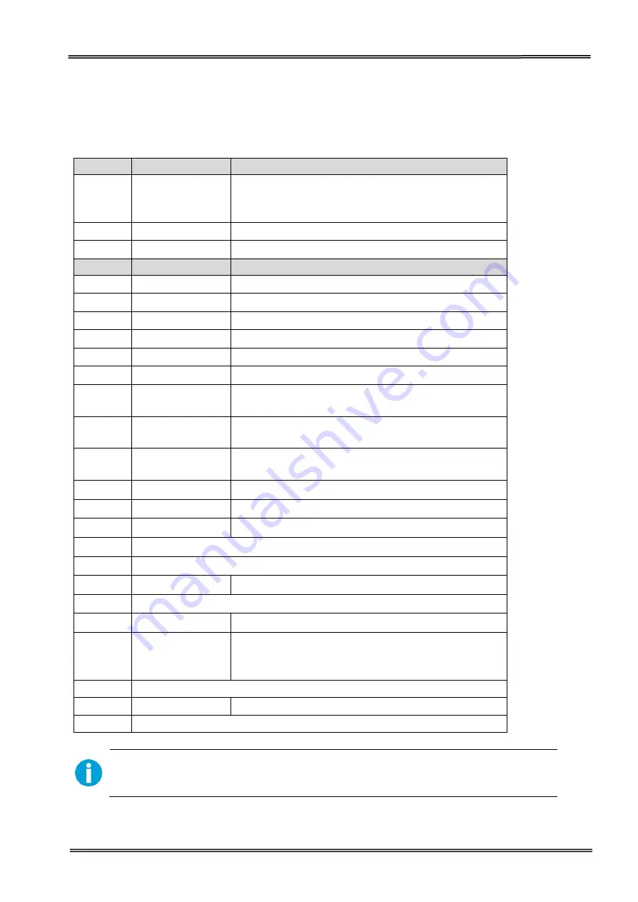
7.4
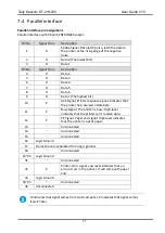
Parallel interface
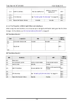
Parallel interface pin assignment
Parallel interface with 36 pin CENTRONICS socket.
Pin No.
Signal From
Description
1
H
Strobe Signal; Data latch pulse, latch the data to
the printer at the rising edge of the negative
pulse.
2
H
Data 0 (The lowest bit)
3
H
Data 1
Pin No.
Signal From
Description
4
H
Data 2
5
H
Data 3
6
H
Data 4
7
H
Data 5
8
H
Data 6
9
H
Data 7 (The highest bit)
10
P
ACK Signal; Printer response signal, indicates that
the printer has received a Data byte.
11
P
Busy Signal; The printer is busy; High level
indicates that the printer can’t receive data.
12
P
PE Signal; Paper end signal; High level indicates
that the printer is out of paper.
13
-
Unconnected
14
-
Unconnected
15
-
Unconnected
16
Logic Ground
17
Frame Ground, separated from logic ground.
18
-
Unconnected
19~30
Logic Ground
31
-
Unconnected
32
P
Printer error signal. Low level indicates that an
error occurs in the printer. It will come with paper
end.
33
Logic Ground
34~35
-
Unconnected
36
Unconnected
H indicates that signal comes from Host computer; P indicates that signal comes
from Printer.
Summary of Contents for DT-210
Page 1: ...User Guide DT 210 230 Thermal Receipt Printer ...
Page 15: ...Tally Dascom DT 210 230 User Guide V1 3 DASCOM REPRESENTATIVES 96 ...
Page 45: ...Tally Dascom DT 210 230 User Guide V1 3 30 5 Click Install 6 Wait for a sec ...
Page 46: ...Tally Dascom DT 210 230 User Guide V1 3 31 7 Installation complete Click Finish ...
Page 48: ...Tally Dascom DT 210 230 User Guide V1 3 33 Enable the Black Mark ...


