


Tally Dascom DT-210/230 User Guide V1.3
72
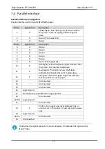
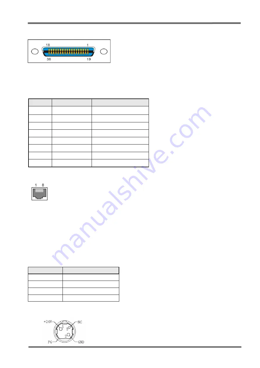
Parallel interface connector diagram
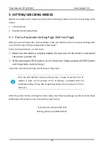
7.5
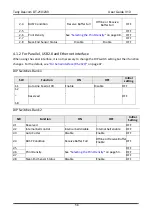
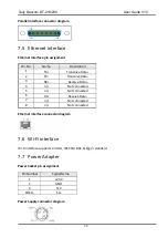
Ethernet interface
Ethernet interface pin assignment
Pin. No.
Name
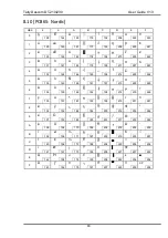
Description
1
TX+
Tranceive Data+
2
TX-
Tranceive Data-
3
RX+
Receive Data+
4
n/c
Not connected
5
n/c
Not connected
6
RX-
Receive Data-
7
n/c
Not connected
8
n/c
Not connected
Ethernet interface connector diagram
7.6
Wi-Fi interface
Wi-Fi interface supports 2.4 GHz, IEEE Std. 802.11b/g/n standard.
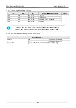
7.7
Power Adapter
Power Socket pin assignment
Pin Number
Signal Name
1
+24 V
2
GND
3
N.C
SHELL
F.G.
Power Supply connector diagram
Summary of Contents for DT-210
Page 1: ...User Guide DT 210 230 Thermal Receipt Printer ...
Page 15: ...Tally Dascom DT 210 230 User Guide V1 3 DASCOM REPRESENTATIVES 96 ...
Page 45: ...Tally Dascom DT 210 230 User Guide V1 3 30 5 Click Install 6 Wait for a sec ...
Page 46: ...Tally Dascom DT 210 230 User Guide V1 3 31 7 Installation complete Click Finish ...
Page 48: ...Tally Dascom DT 210 230 User Guide V1 3 33 Enable the Black Mark ...


