5.14
Replacing the
carriage motor
—
Remove the casing parts (see section 5.1).
—
Remove the ribbon cassette and the print head (see section 5.2).
—
Remove the main controller board (incl. casing, see section 5.4.1).
—
Remove the ribbon drive (see section 5.12).
—
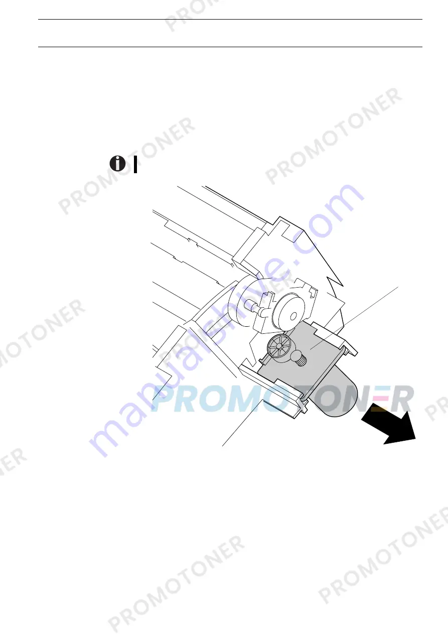
Remove the motor A by pulling it to the left.
When installing the motor, give special attention that the motor cable points to the
right side wall (see also figure).
A
Instructions for disassembly and assembly
Replacing the carriage motor
5-25
Summary of Contents for T2040
Page 1: ...Maintenance Manual Matrix Printer T2040 T2140...
Page 2: ......
Page 6: ......
Page 8: ......
Page 20: ......
Page 40: ......
Page 84: ...6 4 Power supply 120 V 047 832 220 240 V 047 831 Power supply Spare parts and schematics 6 8...
Page 85: ...Spare parts and schematics Power supply 6 9...
Page 89: ...Spare parts and schematics Controller 6 13...
Page 90: ...Controller Spare parts and schematics 6 14...
Page 91: ...Spare parts and schematics Controller 6 15...
Page 92: ...Controller Spare parts and schematics 6 16...
Page 93: ...Spare parts and schematics Controller 6 17...
Page 94: ...Controller Spare parts and schematics 6 18...
Page 97: ...6 6 Panel board 060 477 Clamp panel cable 054 589 Spare parts and schematics Panel board 6 21...
Page 98: ...Panel board Spare parts and schematics 6 22...
Page 101: ...Spare parts and schematics Head connection 6 25...
Page 104: ......


