background image


STOP

Spare parts and schematics

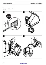
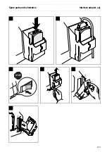
Interface adapter, cpl.

6-31

Summary of Contents for T2150 SprintPro

Page 1: ...Maintenance Manual Matrix Printer T2150 SprintPro A PRODUCT FROM TALLYGENICOM T2250 SprintPro T2150S SprintPro ...

Page 2: ...This page intentionally left blank manuals4you com manuals4you com ...

Page 3: ...y functions when turning on the printer 4 1 4 2 Testmode 4 2 4 2 1 Rolling ASCII 4 3 4 2 2 Interface test Hex Dump 4 4 4 2 3 Setting the Form length Formlen function 4 5 4 2 4 Automatic Gap Adjustment AGA function 4 6 4 2 5 Paper handling Paphand function 4 6 4 2 6 Bidirectional parallel interface CX bid function 4 8 4 2 7 Line wrap Wrap function 4 9 4 2 8 Beep at paper end Sound function 4 9 4 2 ...

Page 4: ...1 1 Replacing the upper part of casing 5 2 5 1 2 Replacing the lower part of casing 5 6 5 2 Replacing the print head 5 8 5 3 Replacing the flap 5 10 5 4 Replacing the electronic components 5 11 5 4 1 Replacing the main controller board incl casing 5 11 5 4 2 Replacing the power supply 5 12 5 4 3 Replacing the panel board 5 14 5 5 Replacing the FAW motor 5 15 5 6 Replacing the paper transport motor...

Page 5: ...ide plate 5 36 5 21 3 Replacing the proof spring 5 36 5 22 Assembling the FAW 5 37 6 Spare parts and schematics 6 1 6 1 Printer 6 1 6 1 1 Housing Panel 6 2 6 1 2 General Arrangement sheet 1 6 4 6 1 3 General arrangement sheet 2 6 6 6 1 4 Power supply 6 8 6 1 5 Controller 6 9 6 1 6 Panel board 6 10 6 1 7 Head connection cpl 6 11 6 1 8 Recommended spare parts 6 12 6 2 Optional Tractor 2 3 6 13 6 2 1...

Page 6: ...Replacing the Friction Rolls 6 22 6 4 2 Replacing the Discharge Axle 6 23 6 4 3 Renewing the Metal Paper Baffle with Guide Foil 6 24 6 4 4 Spare Parts 6 26 6 5 Cutter cpl 6 28 6 6 Interface adapter cpl 6 30 Table of contents IV manuals4you com manuals4you com ...

Page 7: ...nts are required such as step motor for selection of paperpath or for automatic gap adjustment DC motor for carriage transport step motor for paper feed The following features and options will further enhance the printer s capabilities push tractor 1 front standard manual single sheet feeder front standard automatic sheet feeder rear ASF R option automatic sheet feeder front ASF F option push trac...

Page 8: ...This page intentionally left blank manuals4you com manuals4you com ...

Page 9: ...70 cps 20 0 cpi 24 x 10 NLQ Near Letter Quality 180 cps 10 0 cpi 24 x 18 220 cps 12 0 cpi 24 x 15 270 cps 15 0 cpi 16 x 12 135 cps 15 0 cpi 24 x 12 155 cps 17 1 cpi 24 x 18 180 cps 20 0 cpi 24 x 15 LQ Letter Quality 90 cps 10 0 cpi 24 x 36 110 cps 12 0 cpi 24 x 30 135 cps 15 0 cpi 16 x 24 135 cps 15 0 cpi 24 x 24 155 cps 17 1 cpi 24 x 18 180 cps 20 0 cpi 24 x 15 Epson emulation only superscript su...

Page 10: ...hout HRI Q Delta Distance IBM R Code 128 S EAN 128 Large Character Printing LCP US Postnet Barcode Kix Royal Mail Customer Barcode HRI human readable index Emulations Standard MTPL Tally Printer Language Epson LQ 2550 Epson LQ 2170 IBM Proprinter XL24e IBM XL24e AGM Optional on request Resolution 60 to 360 dpi horizontal 90 to 360 dpi vertical Print attributes in all character pitches Double width...

Page 11: ...printer Wide printer 424 mm 600 mm 300 mm 300 mm 399 mm 399 mm Weight Narrow printer Wide printer 10 5 kg 13 2 kg Paper feed Feed speed Feed first line 6 lpi T2150 T2250 T2150S 3 8 inch sec 2 8 inch sec 48 ms 60 ms Reverse motion Up to max form length 22 inch max 1 inch for automatic single sheet feeder Printhead gap Standard Automatic gap adjustment Paper transport Standard Tractor with parking p...

Page 12: ... to 73 Climate IEC 721 3 7 Class 7K1 Storage Temperature 5 to 45 C Rel humidity 5 to 95 Climate IEC 721 3 1 Class 1K3 Transport Temperature 40 to 70 C Rel humidity 5 to 95 Climate IEC 721 3 2 Class 2K4 Printer specifications Specifications 2 4 manuals4you com manuals4you com ...

Page 13: ...tions Printer side Amphenol 57 40360 or compatible Cable side Amphenol 57 30360 or compatible Voltage supply of ex ternal devices on pin 18 U 5 V 10 I 0 5 A max Serial interface Type RS232C interface Synchronization Asynchronous Transmission rate 600 bauds to 19 200 bauds Signal status OFF log 1 3 V to 15 V ON log 0 3 V to 15 V Connection cable Length up to 15 m Interface connections ITT Cannon co...

Page 14: ...20 mm wide printer Form length 76 to 559 mm Manual single sheet feeder Single part forms Weight 80 to 120 g m2 Width 76 to 254 mm narrow printer 76 to 420 mm wide printer Form length 76 to 305 mm Multi part forms to be tested individually Copies 1 5 Weight of original 50 to 60 g m2 Weight of copies 45 to 56 g m2 Weight of bottom sheet 50 to 60 g m2 Thickness max 0 6 mm Width 76 to 254 mm narrow pr...

Page 15: ... the quality mark SM Post and photocopy paper are suitable for use Unsuitable are satin finisch or coated papers imitation art papers and embossed papers Since paper as natural material reacts strongly to environmental influences e g humidity temperature the place of storage should be selected carefully We recommend that this kind of paper should be tested extensively before larger quantities are ...

Page 16: ...printer Standard closed Left paper edge 1 Tractor 1 2 Tractor 2 and tractor 3 options 70 74 1 2 110 114 1 2 Right paper edge min min Adjustable area Narrow printer 266 252 wide printer 420 406 1 2 1 2 Top view Dimensions Specifications 2 8 manuals4you com manuals4you com ...

Page 17: ... 3 option Tractor 1 Tractor 2 option 300 294 150 265 Tear edge Side view left Fanfold paper mode 300 399 185 100 254 Single sheet mode 300 175 228 217 217 Options ASF F and ASF R Specifications Dimensions 2 9 ...

Page 18: ...n with installed interface adapter 45 150 228 105 175 107 Wide 428 Narrow 321 67 47 Wide 463 Narrow 321 91 80 7 72 70 Top view withASF F ASF R and interface adapter Dimensions Specifications 2 10 manuals4you com manuals4you com ...

Page 19: ...oard including parallel and serial interface Print head Head connection Panel board with LC display Paper feed motor Carriage motor Motor FAW AGA paper tray selection CR PE TOF SENSOR Pushbar position check SENSOR CUTTER AGA Timing station LF FAW PRINT HEAD CONTROL BOARD PANEL POWER SUPPL Y X9 Functional description Electronic functions 3 1 ...

Page 20: ...position check The home position sensor checks the position of the pushbar and therefore the se lected paper source There is a position ruler located on the pushbar After switch on the photoelectric barrier in the home position sensor scans this ruler it moves to the next ridge edge and measures the width of the ridge The position of the pushbar is fed back to the firmware in this way Ridge 1 narr...

Page 21: ...e pushbar moves a further 5 5 mm the flat gear 76 on the rear of the side wall is moved by the gear shaft rear 81 see chapter 6 Spare parts and schematics in wards against the wall and thus engages with the bottom gear 93 Tractor 3 is now driven by the gear 77 FAW motor LF motor Position 1 Tractor 2 Gear 82 Pushbar FAW motor LF motor Position 2 Tractor 3 Gear 93 Gear 76 Gear 77 Pushbar Functional ...

Page 22: ...usher on the pushbar moves arm on the friction axle backwards as far as it will go thus switching the friction on The front and rear friction are actuated and both axles are moved from 45 degrees front to 45 degrees rear position FAW motor LF motor Position 31 2 Tractor 1 Gear 82 Gear 79 behind Gear 78 Pushbar FAW motor LF motor Position 6 Friction rear Friction front Pusher Pusher Pushbar Mechani...

Page 23: ... wheel position The paper transport in the ASF F is only activated for printer reverse motion If much paper is to be fed back pushbar position 5 is used Manual sheet feeder The pushbar moves to position 6 and the gear 82 is lifted position 2 and swit ches to friction The manual sheet feeder transports paper to the PE sensor The pushbar then returns to position 5 the gear 82 moves centre between th...

Page 24: ...This page intentionally left blank manuals4you com manuals4you com ...

Page 25: ...Function keys 1 2 and additional 4 after is displayed AGA test refer to section 4 4 This mode is used for checking the function of the AGA feature Function key 1 4 and Online Bootmode You must enter this mode if you want to program flash rom For details see the reference manual on CD ROM section Loading firmware Function key 1 2 3 and Setup Parallelity refer to section 4 5 This test mode is used f...

Page 26: ...et line wrap and beep at paper end ASCII80 ASCII136 Back Next Forml AGA Back Next H Dump Back Next Paphand CX bid Back Next Single Pap back Back Next Wrap Sound Back Next HvyForm SleepMod Back Next Back Next ASCII test with 80 or 136 characters per line Interface test Setting default form length and the Auto matic Gap Adjustment for the print head Settings to facilitate handling paper of poor qual...

Page 27: ...yed You can interrupt the test if you for example want to change the line density by pressing the Online key To exit the ASCII test the printer must be turned off Example for an ASCII test printout If you selected a PS font the printed length of the lines varies This test can also be used to determine and set the optimal print head gap see the reference manual on CD ROM section Setting the print h...

Page 28: ...ormat and in the right in ASCII format Hex Dump mode can only be terminated by switching off the printer Example for a Hex Dump test printout After the transmission you must switch the printer to Offline Any remaining data left in the interface buffer is then printed If you want to stop the Hex Dump printout before switching off the printer press the key Online Testmode Test functions troubleshoot...

Page 29: ...ches or 11 inches Default setting 12 inches for 220 240 V printers 11 inches for 120 V printers The value defined here is set in all three menus and for all paper paths The set ting made here is not changed by loading the default factory settings by pressing all four function keys see reference manual on CD ROM section Key functions when turning on the printer Confirm your setting by pressing the ...

Page 30: ...perties likely to cause problems perforations etc or poor quality paper Put the printer into Testmode and change to the parameter group Paphand CX bid by pressing the key Next three times Select the Paphand menu 4 2 5 1 Increasing the printhead gap Head up Select the Head up menu Possible settings On Off Default setting Off If the parameter is set to On the printhead gap increases during form feed...

Page 31: ...ible settings On Off Default setting Off If the parameter is On the printhead moves out of the form separation perforation zone area on the left as long as the paper is being transported The Pagewid set ting has no influence see above Confirm your settings with the key Set 4 2 5 4 Right hand area Rightzo Select the Rightzo menu Possible settings On Off Default setting Off If the parameter is On th...

Page 32: ...anual 4 2 6 Bidirectional parallel interface CX bid function This function sets the parallel interface of the printer to bidirectional mode IEEE 1284 Nibble mode Put the printer into Testmode and change to the parameter group Paphand CX bid by pressing the key Next three times Select the CX bid menu Possible settings On Off Default setting On CX bid ON sets the parallel interface of the printer to...

Page 33: ...e transmitted per line the characters which cannot be printed on this line are cut off Confirm your settings by pressing the key Set 4 2 8 Beep at paper end Sound function If this function is activated the printer generates a beep when paper is empty Select the Sound menu Possible settings On Off Default setting On When Sound On a beep is generated every second to notify that paper is empty Confir...

Page 34: ...oading the default factory settings Confirm your settings by pressing the key Set 4 2 10 Settings for paper with dark back Pap back function The function Pap back allows printing on paper with a dark back Possible settings normal dark Default setting normal Pap back normal is the standard for normal paper Pap back dark can be set to process paper with a grey back Paper with a completely black back...

Page 35: ...ies the line is printed twice however at single strike 4 2 12 Reduced power in standby mode The function SleepMod reduces the electric power consumption of the printer in standby mode Possible settings On Off Default setting On SleepMod On reduces the electric power consumption of the printer in standby mode to 10 W SleepMod Off ensures the first printing position even after longer printing pauses...

Page 36: ...ld be above 10 ccc result of AGA measurement e g a displayed value 18 represent a normal thickness of a single paper ddd temperature of the print head the value changes between 35 and 120 C eeeee temperature control of CR motor the value should be from 0 to 20 000 A value of 20 000 will reduce print speed To exit the Showon function the printer must be turned off Online Setup 1 2 3 4 aaaaa bb ccc ...

Page 37: ...mple the line lim 300mV max 300mV width 400ms try dist gives the following informations lim 300mV The value of the spurious pulses must be in a range from 1 to 15 The lower the value is the better max 300mV The value of the measuring pulses must be in a range from 1 to 15 The higher the value the better The AGA measuring result is at its most reliable the greater the difference between the lim and...

Page 38: ...llelism measurement is not correct In the display appears In this case you must adjust the adjusting lever item 40 page 6 4 at the right side wall If the value yyy is higher as the value xxx turn the adjusting lever to the rear If the value yyy is lower as the value xxx turn the adusting lever to the front Press any key the printer measures the parallelism again You must repeat this procedure unti...

Page 39: ...ition If these steps do not eliminate the fault Replace the power cord and repeat step 3 Check that power flows at the socket e g using a desk lamp if necessary use a different socket and repeat step 3 Contact your dealer if the printer cannot be powered up Do not attempt to open the printer You might suffer an electric shock The display is lit but the printer does not print 1 Check that the print...

Page 40: ...iously pulling the paper in the correct di rection Before you replace the fanfold paper refer to the instructions in the section Loading paper of the reference manual on CD ROM You should pay special attention to the following points Insert the paper straight After inserting the paper close the tractors Adjust the tractors the paper should be positioned in the tractors straight but without tension...

Page 41: ...ection Setting the print head gap Prints undefined characters 1 Check that the interface plug is correctly connected to the computer and to the printer 2 Check that the proper emulation and the correct character set country CG table or character set is selected in the Setup menu 3 Check the length of the interface cable see the reference manual on CD ROM chapter Technical specifications The first ...

Page 42: ...on Note down the display message For further details refer to section 4 6 4 Display Message Hardware Alarm Overrun Error Received data which has not yet been printed is overwritten with new data Check that the correct busy protocol e g XON XOFF is set in the menu Serial interface protocol Check the interface cable see the reference manual on CD ROM section Con necting the printer to the computer a...

Page 43: ...osition You are informed when the fanfold paper is in the park position Tear paper off Note for the operator to tear off the paper automatically positioned at the tear off edge Load paper from single Paper is not available in the selected paper path Data is in the interface receiver buffer Remove paper in xxx The paper path has been changed xxx indicates the paper path Please remove any remaining ...

Page 44: ...e the better A value of 0 switch the printer to OFFLINE and display check Ribbon but produce no HW Alarm Line 1 Pos 9 slash Line 1 Pos 10 to 13 cccc result of AGA measurement e g a displayed value 18 represent a normal thickness of a single sheet paper Line 1 Pos 14 to 16 ddd in HW Alarm condition the very right value must be a zero Line 2 Pos 1 to 3 eee 1 cut task active 8 FAW carriage is blocked...

Page 45: ...horizontal timing belt can be tested value of actual position is changing The Task Control Codes for eee fff and ggg may occur as combinations for each section Example ggg display code 160 Meaning AGA adjustment 128 and FAW 32 is active Test functions troubleshooting and maintenance Troubleshooting 4 21 justmanuals com ...

Page 46: ...directly from the outside Open the small compartment below the po wer supply connector with a screwdriver and pull out the compartment completely Remove the defective fuse and replace it by a new fuse of the same type The fuse ratings are specified on the prin ter type plate which is mounted above the power connector on the rear T2 5AH 250V 4 7 2 Cleaning the housing Clean the printer housing with...

Page 47: ...n deposits with a soft brush Check that any paper has been removed from the tractors 4 7 4 Platen Remove the ribbon Carefully clean the platen with platen roller cleaner available from dealers Test functions troubleshooting and maintenance Maintenance 4 23 ...

Page 48: ...0S prin ters 5 million characters for the T2250 printer and 10 million characters using the ribbon of the T2255 printer 4 7 6 Upper friction Clean the rollers of the upper friction as necessary with a mild cleaning agent and a soft lint free cloth 4 7 7 Carriage shafts Carriage shafts must not be greased otherwise damage will occur on the printer STOP Maintenance Test functions troubleshooting and...

Page 49: ...respective parts A Bores E Pin for spreader gear B Pin for toothed wheel F Shell 2x C Pins G Running surface 3x D Cam on switching axle H Groove Lubricate all greasing positions with Polylub GLY 801 Mat no 2450 Test functions troubleshooting and maintenance Lubrication 4 25 ...

Page 50: ...This page intentionally left blank manuals4you com manuals4you com ...

Page 51: ...ow the printer parts were mounted before Avoid touching the electronic components unless you are discharged on a protecti ve ground Suggested tools Hook 395 850 Phillips screwdriver medium Screwdriver small Flat nosed pliers When left and right are mentioned in the text this refers to the printer as seen from the front STOP STOP Instructions for disassembly and assembly 5 1 Normally assembling is ...

Page 52: ...e casing parts 5 1 1 Replacing the upper part of casing Remove the front cover Remove the bottom cover tractor 1 Replacing the casing parts Instructions for disassembly and assembly 5 2 manuals4you com manuals4you com ...

Page 53: ... Remove the upper cover rear Remove the rear cover Instructions for disassembly and assembly Replacing the casing parts 5 3 ...

Page 54: ...emove it Use a screwdriver to unlock the panel as shown in the illustration and carefully remove it Be carefull while doing the above mentioned step You may damage the panel cable Replacing the casing parts Instructions for disassembly and assembly 5 4 manuals4you com manuals4you com ...

Page 55: ... plug B Use a screwdriver to unlock the upper casing as shown in the illustration tilt it in an angle of approx 45 degrees to the rear lift it upward and remove it Be careful about the panel cable B A Instructions for disassembly and assembly Replacing the casing parts 5 5 ...

Page 56: ...n 5 1 1 Release the four rubber snaps suspension A of the print module using special tool Hook position also see page 5 7 Remove the ESD connections right hand B and left hand C A C B Replacing the casing parts Instructions for disassembly and assembly 5 6 manuals4you com manuals4you com ...

Page 57: ...nector together and unplug the cable A Lift the whole printer mechanic with both hands straight upward and put it carefully on a stable place A Instructions for disassembly and assembly Replacing the casing parts 5 7 ...

Page 58: ...ion 5 1 1 Move the carriage A to the left Remove the ribbon cassette Lift the flap B Loosen the clip C at the print head D Press the left shank of the clips inwards B A D C Replacing the print head Instructions for disassembly and assembly 5 8 manuals4you com manuals4you com ...

Page 59: ... Pull out the printhead carefully Instructions for disassembly and assembly Replacing the print head 5 9 ...

Page 60: ...1 1 Turn the flap A upwards to a vertical position beyond the snap point and pull off Be careful with the foils of the flap if they are damaged the paper feed may be disturbed A Replacing the flap Instructions for disassembly and assembly 5 10 manuals4you com manuals4you com ...

Page 61: ...g Remove the casing parts see section 5 1 Press the two latches A of the cover controller casing inwards Lift the cover controller casing and press at point B inwards Remove the casing carefully to the left A B Instructions for disassembly and assembly Replacing the electronic components 5 11 ...

Page 62: ... cable panel G 5 4 2 Replacing the power supply Remove the casing parts see section 5 1 Remove the main controller board see section 5 4 1 Unplug the connector A cable controller and B cable power connection A B D C E F G A B Replacing the electronic components Instructions for disassembly and assembly 5 12 manuals4you com manuals4you com ...

Page 63: ...tch Screw out the grounding wire cable D with a phillips screwdriver Loosen the retaining clips carefully with a flat nosed pliers and remove the power supply C D Instructions for disassembly and assembly Replacing the electronic components 5 13 ...

Page 64: ...l board Remove the panel see section 5 1 1 Use a screwdriver to unlock the two noses A and remove panel board A Replacing the electronic components Instructions for disassembly and assembly 5 14 manuals4you com manuals4you com ...

Page 65: ...rd incl casing see section 5 4 1 Remove the cable shield A Press the seesaw B together at its axis C move the top to the left and release the two clips D Remove the seesaw B Turn the FAW motor clockwise and remove it B D C D A C Instructions for disassembly and assembly Replacing the FAW motor 5 15 ...

Page 66: ...s see section 5 1 Remove the main controller board incl casing see section 5 4 1 Remove the screws A of the paper transport motor B and remove it A B Replacing the paper transport motor Instructions for disassembly and assembly 5 16 manuals4you com manuals4you com ...

Page 67: ... incremental strip on the right side Guide a small srewdriver into the hole A and press to the left Remove the incremental strip to the left When installing the incremental strip make sure that the long empty section B is po sitioned lefthand A B Instructions for disassembly and assembly Replacing incremental strip 5 17 ...

Page 68: ...s on the back side of the AGA sensor case A carefully with an srewdriver and remove it by pulling up Disconnect the AGA sensor cable B When installing position the AGA sensor in its case and press it down A B Replacing the AGA sensor Instructions for disassembly and assembly 5 18 manuals4you com manuals4you com ...

Page 69: ...e sensor holder A by pressing inwards the nose B and pulling upwards Disconnect the timing station sensor cable C and remove the timing station sensor D When installing the timing station sensor make sure that the cable is connected correctly contact side facing rear part of printer A B D C Instructions for disassembly and assembly Replacing timing station sensor 5 19 ...

Page 70: ...tion 5 4 1 Remove the home position sensor A by pressing catch B with a screwdriver When installing the home position sensor make sure that the cable is connected correctly contact side facing left side plate of the printer A B Replacing the home position sensor Instructions for disassembly and assembly 5 20 manuals4you com manuals4you com ...

Page 71: ...n drive see section 5 12 Remove the carriage motor see section 5 14 Move the carriage to the left Remove the transparent cable holder A Use a screwdriver to release the cable holder B from the two noses and move it to the left Remove the cable holder C in the carriage Remove the printhead cable D Take care of the isolation shield E D A B C E Instructions for disassembly and assembly Replacing the ...

Page 72: ...ght side Push the key B in direction to the printer front and remove it Turn the ribbon drive C to the left to loosen the toothed belt D Twist out the ribbon drive C by lifting it slightly up from the bottom Remove the toothed belt on the left side from the motor guide E push it through the left side plate release the belt clamp at the carriage and remove the ribbon drive C STOP A C B D E Replacin...

Page 73: ...section 5 8 and 5 9 Remove the printhead cable see section 5 11 Remove the ribbon drive see section 5 12 Remove the carriage motor see section 5 14 Push the front carriage shaft A from the snap arrest B Pull the front carriage shaft out to the right and remove it Caution The ground spring is sharp A B STOP Instructions for disassembly and assembly Replacing the carriage 5 23 ...

Page 74: ...djusting lever D until the two noses face the slots and remove it Pull the carriage shaft E first to the right lift it at the left side and pull it out of carriage F C D E F Replacing the carriage Instructions for disassembly and assembly 5 24 manuals4you com manuals4you com ...

Page 75: ...ove the main controller board incl casing see section 5 4 1 Remove the ribbon drive see section 5 12 Remove the motor A by pulling it to the left When installing the motor give special attention that the motor cable points to the right side plate see also figure A Instructions for disassembly and assembly Replacing the carriage motor 5 25 ...

Page 76: ...driver to release the clamp A on the right side of the printing bar B Remove the printing bar B slightly forward and then to the right out of the left holder Remove the corners C Remove the bearing D A B C D B C Replacing the printing bar Instructions for disassembly and assembly 5 26 manuals4you com manuals4you com ...

Page 77: ...ain controller board incl casing see section 5 4 1 Remove the flap see section 5 3 Remove the printing bar see section 5 13 Take out the PE sensor A upward Make sure when assembling that the cable B is properly in place A B Instructions for disassembly and assembly Replacing the PE sensor 5 27 ...

Page 78: ...5 2 Remove the flap see section 5 3 Remove the carriage see section 5 13 Remove the printing bar see section 5 15 Remove the PE sensor see section 5 16 Release the three four narrow wide printer clips A and remove the friction drive shaft front B A B Replacing the Friction Drive Instructions for disassembly and assembly 5 28 manuals4you com manuals4you com ...

Page 79: ...ch of the two three narrow wide printer latches D forward and remove it by pulling up Start on the right end Remove the two three narrow wide printer roller springs E and the friction axles F C D F E D C Instructions for disassembly and assembly Replacing the Friction Drive 5 29 justmanuals com ...

Page 80: ... as soon as possible to the left Press the holder B on the right side back slightly and move the shaft A upwards To take out the shaft A pull it to the right Caution The ground spring is sharp STOP A B Replacing the tractor Instructions for disassembly and assembly 5 30 manuals4you com manuals4you com ...

Page 81: ...E on the right side back slightly and move the shaft D upwards To take out the shaft D and the tractors first move the shaft to the right then remove it C D E Instructions for disassembly and assembly Replacing the tractor 5 31 manuals4you com manuals4you com ...

Page 82: ...4 1 Remove the tractor see section 5 18 Use the special tool Hook to release the axle A of the switch paper guide B Use a flat nosed pliers to pull out the axis of the switch paper guide through the sidewall right hand B A Replacing the switch paper guide Instructions for disassembly and assembly 5 32 manuals4you com manuals4you com ...

Page 83: ...e carriage see section 5 13 If you move the carriage to the left side as far as it will go remove the print head and the ribbon guide it is not necessary to remove the carriage and the carriage shaft Remove the printing bar see section 5 15 Remove the PE sensor see section 5 16 Use a screwdriver to unlock the paper guide A at the right side Move the paper guide upwards and remove it STOP A Instruc...

Page 84: ...g the holer C Move the driving shaft B first to the right then remove it Make sure that the position of the push bar selected paper path is not Tractor 2 B C Replacing the paper transport Instructions for disassembly and assembly 5 34 manuals4you com manuals4you com ...

Page 85: ...ith FAW Remove all parts as described in 5 1 to 5 20 Press holder A and at the same time unlock tongue A by pulling out of holder A Caution The holders should be pressed at their ends Do not press too heavily because they could break Repeat this procedure with holders B and C Remove the left side plate with FAW and gears STOP A B C A Instructions for disassembly and assembly Replacing the side pla...

Page 86: ...icture below using flat nose pliers until it slips out of the case When you reassemble the proof spring it is recommended to use a new spring which is part of a new spare part set in order to improve the function of the auto matically paperpath selection The spare part set contains two proof springs two screws and four disks Place two disks on each screw and then fix the proof spring item 75 insid...

Page 87: ...es down and the bottom edge towards you Insert the toothed wheel A item 96 positioned under the push bar If necessary attach the slide FAW B item 71 and the position ruler C item 95 to the push bar D item 70 A B C D Instructions for disassembly and assembly Assembling the FAW 5 37 ...

Page 88: ... recess 1 on the push bar engages with the guide provided in the side plate 2 For this purpose the mark for position 1 see also page 3 3 upper drawing must be at about 3 mm to the left of the mark on the side plate Take care not to move or turn the gear shaft rear E Then slide the push bar into position 1 Insert the gear shaft front F in such a way that the ring with the pins points away from you ...

Page 89: ...ear shaft front F Make sure that the straight sides of the semidiscs of both shafts point to the same direction and continue to be at an angle of 90 to the side plate Finally mount the transverse connection plate item 52a and complete the left side plate D F E Instructions for disassembly and assembly Assembling the FAW 5 39 ...

Page 90: ...This page intentionally left blank manuals4you com manuals4you com ...

Page 91: ...n narrow printer second column wide printer X in second and or third column means part is the same like in the first column 4 The classification of parts 5 The quantity used in printer When ordering parts it is essential to specify a part number and designation factory repair only depot repair standardized parts _ C parts printer specific parts recommended spare parts A B C D E Spare parts and sch...

Page 92: ...6 1 1 Housing Panel a Printer Spare parts and schematics 6 2 manuals4you com manuals4you com ...

Page 93: ... 200 X X B 1 11 Foil manual paper tray 060 322 060 323 060 322 B 1 12 Push push snapper 716 227 X X B 1 13 Foot 052 025 X X B 4 14 ESD connection LH 060 415 060 284 060 415 B 1 15 ESD connection RH 060 416 X X B 1 16 Shield casing power 060 283 X X B 1 17 Power switch 710 330 X X A C 1 18 Suspension 060 496 X X B 4 19 Power connection 047 892 X X B 1 19a Fuse main 2 5 A HT ker 5x20 710 405 X X A B...

Page 94: ...6 1 2 General Arrangement sheet 1 Printer Spare parts and schematics 6 4 manuals4you com manuals4you com ...

Page 95: ...8 B 1 48 Switch paper guide 060 316 X X B 2 3 49 Bush switch paper guide 716 180 X X C 1 50 DC motor CR cpl 061 439 X X A B 1 51 Guide wheel toothed belt 461 662 X X B 1 52 Carriage shaft cpl 060 484 060 485 060 484 A B 1 52a Transverse connection plate 060 201 060 200 060 201 B 1 53 Ribbon drive with belt cpl 460 299 460 211 460 299 A B 1 54 ESD spring printing bar 061 065 X X B 2 55 Printing bar...

Page 96: ...6 1 3 General arrangement sheet 2 91a 75b 75c 86b 86a 91a Printer Spare parts and schematics 6 6 manuals4you com manuals4you com ...

Page 97: ... Kit Motor FAW 070 063 X X A B 1 85 Sensor position ruler 047 823 X X A B 1 86a Cable shield 87 Cable power unit controller 047 961 047 705 047 961 A B 1 88 Cover controller casing 060 360 X X B 1 89 Controller Kit incl casing 070 003 070 003 070 004 A B D 1 91 Stepper motor LF cpl 048 949 X X A B 1 91a Screw EJOT PT K 40 x 10 1452 92 Guide LF motor 054 186 X X B 1 93 Toothed wheel Z60 16 060 406 ...

Page 98: ...6 1 4 Power supply 120 230 V 448 473 Printer Spare parts and schematics 6 8 manuals4you com manuals4you com ...

Page 99: ...6 1 5 Controller FLASH version 180 dpi only Printer type UCL Controller Firmware Contr kit T2150 2250 0 048 780 048 787 070 003 T2150S 0 048 780 048 788 070 004 Spare parts and schematics Printer 6 9 ...

Page 100: ...6 1 6 Panel board part of panel cpl item 8 page 6 3 Clamp panel cable 054 589 blue strip must face down Printer Spare parts and schematics 6 10 manuals4you com manuals4you com ...

Page 101: ...6 1 7 Head connection cpl Narrow printer 060 479 Wide printer 060 478 X5 X6 from controller Spare parts and schematics Printer 6 11 ...

Page 102: ...9 A B 1 31 Sensor AGA cpl 060 480 X X A B 1 32 Carriage cpl 060 486 X X A B 1 46 Tractor set LH RH support 060 487 X X A B 1 50 DC motor CR cpl 061 439 X X A B 1 52 Carriage shaft cpl 060 484 060 485 060 484 A B 1 53 Ribbon drive with belt cpl 460 299 460 211 460 299 A B 1 57 Flap mounted upper friction cpl 460 542 460 543 461 554 A B 1 62 Sensor PE 047 820 X X A B 1 84 Kit Motor FAW 070 063 X X A...

Page 103: ... program 6 2 2 Installing the tractor 2 Raise the front cover Installation must be performed with the gear on the tractor on the left side Insert the tractor 2 with the pins on the left and right in parallel to the stop into the guides provided on the printer Press the tractor down until the front pins click into place on the left and right Loading paper is described in the Reference Manual chapte...

Page 104: ...d from the front side of the printer Insert the tractor 3 with the pins on the left and right in parallel to the stop into the guides provided on the printer Press the tractor down until the rear pins click into place on the left and right Loading paper is described in the Reference Manual chapter Loading paper Optional Tractor 2 3 Spare parts and schematics 6 14 manuals4you com manuals4you com ...

Page 105: ...ength 76 to 559 mm Continuous paper tractor 2 tractor 3 multi layer to be tested individually Copies 1 6 Weight of original 45 to 65 g m2 Weight of copies 45 to 56 g m2 Weight of the last sheet 45 to 65 g m2 Thickness max 0 6 mm Paper width 76 to 406 mm Form length 76 to 559 mm Spare parts and schematics Optional Tractor 2 3 6 15 ...

Page 106: ... Spare parts T2150 Item Name T2150S T2250 Class Qty 1 Tractor set cpl 060 487 X B 1 2 Toothed wheel Z40 060 407 X B 1 1 2 Optional Tractor 2 3 Spare parts and schematics 6 16 manuals4you com manuals4you com ...

Page 107: ...ll no longer be possible to select them with the paper path quick selection function If the ASF F is deinstalled in the PapOpt menu the prin ter will reactivate the Single paper path automatically leaving Trac2 deactivated 6 3 2 Installing the ASF F Insert the two paper support brackets 1 into the openings provided in the paper guides Mount the paper support s to the holder the narrow printer is p...

Page 108: ... pins on the left and right in parallel to the stop into the guides provided on the printer Press the single sheet feeder down on the left and right until the front pins click into place on the left and right Optional automatic sheet feeder front ASF F Spare parts and schematics 6 18 manuals4you com manuals4you com ...

Page 109: ...dividually Copies 1 3 Weight of original 50 to 60 g m2 Weight of copies 45 to 56 g m2 Weight of the last sheet 50 to 60 g m2 Thickness max 0 46 mm Paper width 100 to 365 mm Form length 100 to 305 mm Envelopes Width 100 to 365 mm Length 100 to 305 mm Thickness 0 32 mm Paper capacity max 50 sheets 80 g m2 Spare parts and schematics Optional automatic sheet feeder front ASF F 6 19 ...

Page 110: ...6 3 4 Spare parts 1 2 4 3 7 8 24 6 5 9 10 11 12 13 14 15 16 17 18 19 20 25 21 22 23 23 25 25 Optional automatic sheet feeder front ASF F Spare parts and schematics 6 20 manuals4you com manuals4you com ...

Page 111: ... 10 Casing right 062270 X B 1 15 Friction roller 053852 X B 2 17 Toothed wheel m 0 75 Z 34 060377 X B 1 21 Paper guide 062217 X B 1 22 Paper guide extension 062275 X B 1 24 Leaf spring 060497 X B 2 X same part no like in first column Spare parts and schematics Optional automatic sheet feeder front ASF F 6 21 ...

Page 112: ...l screwdriver and insert into the lock slots B Caution The gears are loose Remove brake lever C remove axle D on the left and pull off friction rolls E Caution Make sure that both rolls are lying in the guides F Clamp panel cable 054 589 blue strip must face down Optional automatic sheet feeder rear ASF R Spare parts and schematics 6 22 manuals4you com manuals4you com ...

Page 113: ... 1 Take off left casing see section 8 1 1 1 Caution Gear wheels are loose inside Pull gear C from snap lock of the axle Open snap lock with a small screwdriver Pull axle D to the right off the left wall Spare parts and schematics Optional automatic sheet feeder rear ASF R 6 23 ...

Page 114: ...move right casing Take a small screwdriver and insert into the lock slots A Push the right side frame B outward Pull paper baffle C from the fastening Optional automatic sheet feeder rear ASF R Spare parts and schematics 6 24 manuals4you com manuals4you com ...

Page 115: ...This page intentionally left blank Spare parts and schematics Optional automatic sheet feeder rear ASF R 6 25 ...

Page 116: ...6 4 4 Spare Parts Optional automatic sheet feeder rear ASF R Spare parts and schematics 6 26 manuals4you com manuals4you com ...

Page 117: ...o Part no Class Qty ASF R complete 061800 061799 B 1 4 Toothed wheel Z 16 052291 X B 1 23 Friction roller 053852 X B 1 X same part no like in first column Spare parts and schematics Optional automatic sheet feeder rear ASF R 6 27 ...

Page 118: ...6 5 Cutter cpl 14 12 17 15 16 11 10 8 7 6 9 5 3 13 2 1 4 1a 13 Cutter cpl Spare parts and schematics 6 28 manuals4you com manuals4you com ...

Page 119: ...cable cpl 061 428 A B 1 6 Bottom casing 060 564 B 1 7 Lever LH cpl 060 567 B 1 8 Lever RH cpl 060 568 B 1 9 Connector holder plate 061 204 B 1 10 Carriage shaft 054 680 B 1 11 Carriage kit cpl 061 207 A B 1 13 Side plate plastic RH LH 061 217 B 2 15 Paper guide cpl 060 571 B 1 16 Paper out axle cpl 061 427 B 1 17 Cutting bar cpl 060 572 A B 1 Foil set foils of item 6 15 17 061 993 Spare parts and ...

Page 120: ...6 6 Interface adapter cpl 061 925 STOP Interface adapter cpl Spare parts and schematics 6 30 manuals4you com manuals4you com ...

Page 121: ...STOP Spare parts and schematics Interface adapter cpl 6 31 ...

Page 122: ...This page intentionally left blank manuals4you com manuals4you com ...

Page 123: ...rs or inaccuracies of information herein TRADEMARK ACKNOWLEDGEMENTS IBM is a trademark of International Business Machines Corporation EPSON is a trademark of Epson America Incorporated DEC is a trademark of Digital Equipment Corporation Centronics is a trademark of Centronics Data Computer Corporation MS DOS is a trademark of Microsoft Corporation Windows Windows 95 Windows 98 Windows 2000 Windows...

Page 124: ...9 02 48608 1 Fax 39 02 48601 141 http www tallygenicom it SPAIN TallyGenicom SRL Joaquin Lorenzo 4 Local 28033 Madrid España Phone 34 902 196 183 Fax 34 913 739 943 http www tallygenicom es SINGAPORE TallyGenicom Pte Ltd 63 Hillview Avenue 08 22 Lam Soon Industrial Building Singapore 669569 Phone 65 6760 8833 Fax 65 6760 1066 http www tallygenicom com sg U S A TallyGenicom 4500 Daly Drive Suite 10...

Reviews: