General
Functional Description
3-2
3.1.4
Data Transfer
The main difference between the parallel and the optional serial interface is the form
in which the data bytes are transfered. The serial interface transfers bits in a row, one
after the other. Theoretically you only need three connections for this form of data
transfer. In the parallel interface the data transfer of the 8 bits (1 byte) is completed
simultane-ously through 8 parallel connections. At least 11 connections between the
computer and the printer are necessary for this procedure.
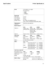
With the parallel Centronics interface data up to 100.000 bytes /seconds theoretically
can be transfered. Actually the printer opperates with a maximum transfer frequency
of approx. 30.000 bytes/second. This “Data Flow”, depending on the adjustment of
the input buffer (0-128 KB) on your printer, can be temporarily stored.
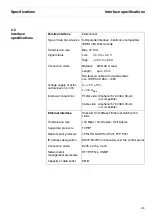
When using your printer in a local network with Ethernet connections and the TCP/IP
protocol, you have to assign several address informations.
The assumed address space corresponds to the TCP/IP adress, class C,
192.168.1.xxx.
The subnet mask to be used is 255.255.255.0.
The address of the router, or gateway, is 0.0.0.0, if not available.
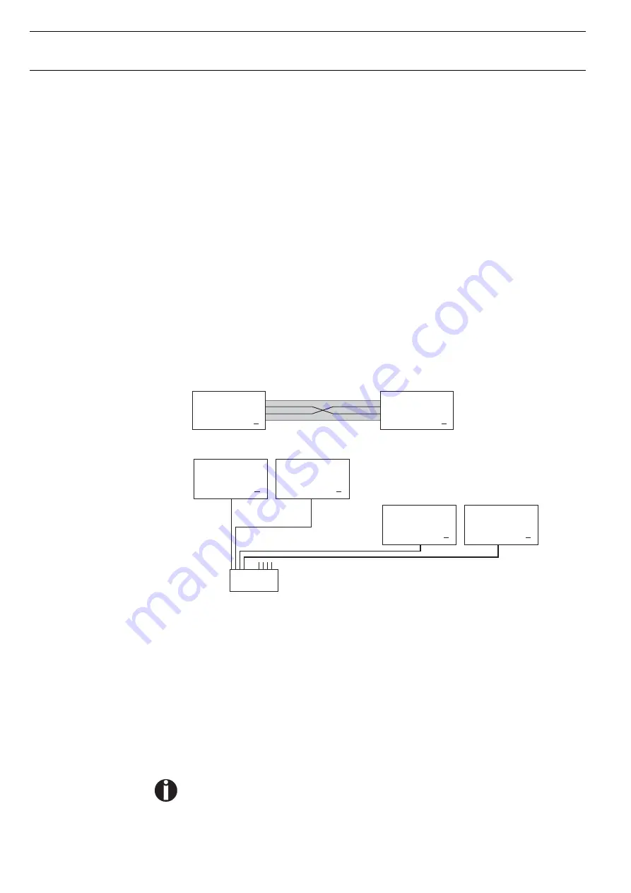
3.1.4.1
Example of a printer
connected to a computer
in an Ethernet
3.1.4.2
Example of several de-
vices in an Ethernet
3.1.5
Monitoring
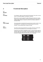
The most important functions are monitored with sensors, microswitches and elec-
trical monitoring circuits. These are constantly checked, processed by an internal
logic and indicated on the display.
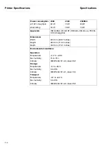
To prevent an overheating of the printhead, 12 coils of the 24 electromagnets are
monitored. If the temperature reaches a value above 130 °C the speed of the printer
is automatically slowed down. As soon as the printhead has cooled the printer works
with high speed again.
If a coil becomes defective, this is recognized by the firmware and shown on the
display (Head defect, THS Error, Head Hot permanently).
Obviously a worn out print head may cause “Head Hot” message as well.
For safety reasons the top cover is also monitored. If you should open the top cover
during printing operation, then the printout is momentary stopped (to avoid injuries).
When you close the cover again the printout is continued without loss of data.
Caution:
!
Twisted-pair cable required
Computer 1
IP: 192.168.1.1
Printer 1
IP: 192.168.1.2
HUB
4-fold or 8-fold
. . .
Printer 1
IP: 192.168.1.3
Printer 2
IP: 192.168.1.4
. . .
Computer 2
IP: 192.168.1.2
Computer 1
IP: 192.168.1.1
Summary of Contents for 2365
Page 1: ...Maintenance manual Matrix printer 2365 2380...
Page 2: ...This page intentionally left blank...
Page 8: ...This page intentionally left blank...
Page 10: ...This page intentionally left blank...
Page 20: ...This page intentionally left blank...
Page 32: ...Mechanical Functions Functional Description 3 12 right mark mark mark...
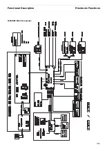
Page 35: ...Functional Description Electronic Functions 3 15 2365 2380 Electronic groups...
Page 128: ...This page intentionally left blank...
Page 134: ...Mechanical Adjustments Adjustments 6 6...
Page 136: ...Electrical Adjustments Adjustments 6 8...
Page 142: ...Housing Spare Parts and Schematics 7 2 7 1 Housing 7 1 1...
Page 144: ...Basic Printer Spare Parts and Schematics 7 4 7 2 1 Basic Printer 1 3 36...
Page 145: ...Spare Parts and Schematics Basic Printer 7 5 Basic Printer 2 3 462646...
Page 146: ...Basic Printer Spare Parts and Schematics 7 6 Basic Printer 3 3...
Page 151: ...This page intentionally left blank...
Page 164: ...Option Recognition Spare Parts and Schematics 7 24 7 10 Option Recognition...
Page 168: ...This page intentionally left blank...
Page 170: ...Tractor Complete Rear Tractor 2T Model 8 2 8 2 Tractor Complete 4 1...
Page 172: ...This page intentionally left blank...
Page 174: ...Cutting Device Option Specifications 9 2 14 6 4 12 1 5 6 11 7 13 7 8 17 2 9 3 16 15 4...
Page 176: ...This page intentionally left blank...
Page 177: ...2nd Front Tractor option 10 1 10 2nd Front Tractor option...
Page 179: ...Printer Stand Overview 11 1 11 Printer Stand 11 1 Overview...
Page 180: ...Installing the Printer Stand Printer Stand 11 2 11 2 Installing the Printer Stand 1 2 3 4...
Page 181: ...Printer Stand Installing the Printer Stand 11 3 6 8 7 5...
Page 182: ...Installing the Printer Stand Printer Stand 11 4 9 10...


