Electronic Functions
Functional Description
3-20
2.2 Phase 2, Data transmission phase
This phase is activated even after phase 1. A string of characters is transferred from
the printer to the PC, which immediately describes the printer type, the manufacturer,
the device class and some sort of compatibility.
Procedure
– SELECTIN and AUTOFEED are set to low by the PC at the same time
– Within 35 ms the printer reacts with SELECT, ERROR, PAPEREND and DONE set
to low.
– PC transmits one Byte with a STROBE pulse and sets AUTOFEED to high.
– This byte will be analyzed by the printer. If everything was ok the byte should be
04hex which means that PC is demanding the identification of the printer in Nibble
Mode. The printer agrees setting PAPEREND to low and DONE to high.
– PC answers setting AUTOFEED to low.
– Now the initial procedure starts by sending the characters. The string is built up in
a way that the first two bytes are indicating the total length of the string (including
the first two counter bytes). MSB first then LSB is transmitted followedby the char-
acters.
– Each byte starts by putting bits 0 - 3 to the control signals (see above).
– This Nibble (half - byte) is released setting DONE to low.
– The acknowledge of PC is done by setting AUTOFEED to high.
– As soon the printer recognizes the acknowledge DONE is put back to high.
– As a result the PC sets AUTOFEED back to low.
– Now bits 4 - 7 are sent using the signal lines.
– This Nibble (half - byte) is released setting DONE to low.
– The acknowledge of PC is done once more by setting AUTOFEED to high.
– As long as there are data to be transmitted the printer sets now
PAPEREND,ERROR, SELECT and BUSY to low and DONE once more to high.
– The acknowledge of the PC is performed by setting AUTOFEED to low.
– Now the next nibble can be sent and the procedure is repeated.
– If there are no more data to be transferred after the last Nibble (half - byte) the
printer is setting ERROR to high, SELECT, PAPEREND and BUSY to low.
– This will be release setting DONE to high.
– Now the termination of the data transmission phase is starting. The PC sets
SELECTIN signal to low.
– The printer reacts – different than in the negotiation phase – with SELECT set to
low, BUSY set to high and – after a short delay – DONE set to low.
– The printer is setting ERROR and SELECT according to the actual status in normal
Centronics mode and after that DONE back to high.
– PC reacts setting AUTOFEED to high.
– At the very end of the data transmission phase the printer sets BUSY and DONE
according to the actual state in normal Centronics mode.
– Now everything is in normal state again and the transmission of the printer identi-
fication is completed.
2
3
2
3
5
3
5
3
6
3
3
X
6
3
7
3
5
B
4
5
2
A
C
C
C
V
2
7
3
6
1
8
2
1
2
1
2
D
N
G
D
N
G
9
C
2
1
N
0
0
1
8
5
R
K
0
1
1
2
0
1
0
1
1
3
1
3
4
3
4
3
0
2
0
2
9
9
0
3
0
3
9
1
9
1
8
8
9
2
9
2
8
1
8
1
7
7
8
2
8
2
7
1
7
1
6
6
6
2
6
2
6
1
6
1
5
5
5
2
5
2
5
1
5
1
4
4
3
2
3
2
3
1
3
1
2
2
4
2
4
2
4
1
4
1
3
3
2
2
2
2
2
1
2
1
1
1
1
1
1
1
6
3
D
N
G
E
G
D
N
9
1
R
B
B
C
2
2
2
1
1
1
N
T
L
U
A
F
I
T
C
E
L
E
S
N
F
R
E
T
NI
.
R
A
P
D
N
G
X
Y
S
U
B
TI
NI
D
N
G
X
N
E
N
O
D
D
N
G
D
N
G
D
N
G
8
DI
D
N
G
D
N
G
7
DI
D
N
G
X
C
C
V
6
DI
D
N
G
D
N
G
E
5
DI
D
N
G
D
N
G
4
DI
D
N
G
3
DI
D
N
G
D
F
O
T
U
A
2
DI
1
DI
D
N
G
E
P
L
E
S
N
E
B
O
R
T
S
3
3
3
3
Summary of Contents for 2365
Page 1: ...Maintenance manual Matrix printer 2365 2380...
Page 2: ...This page intentionally left blank...
Page 8: ...This page intentionally left blank...
Page 10: ...This page intentionally left blank...
Page 20: ...This page intentionally left blank...
Page 32: ...Mechanical Functions Functional Description 3 12 right mark mark mark...
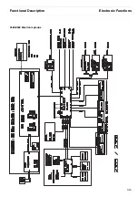
Page 35: ...Functional Description Electronic Functions 3 15 2365 2380 Electronic groups...
Page 128: ...This page intentionally left blank...
Page 134: ...Mechanical Adjustments Adjustments 6 6...
Page 136: ...Electrical Adjustments Adjustments 6 8...
Page 142: ...Housing Spare Parts and Schematics 7 2 7 1 Housing 7 1 1...
Page 144: ...Basic Printer Spare Parts and Schematics 7 4 7 2 1 Basic Printer 1 3 36...
Page 145: ...Spare Parts and Schematics Basic Printer 7 5 Basic Printer 2 3 462646...
Page 146: ...Basic Printer Spare Parts and Schematics 7 6 Basic Printer 3 3...
Page 151: ...This page intentionally left blank...
Page 164: ...Option Recognition Spare Parts and Schematics 7 24 7 10 Option Recognition...
Page 168: ...This page intentionally left blank...
Page 170: ...Tractor Complete Rear Tractor 2T Model 8 2 8 2 Tractor Complete 4 1...
Page 172: ...This page intentionally left blank...
Page 174: ...Cutting Device Option Specifications 9 2 14 6 4 12 1 5 6 11 7 13 7 8 17 2 9 3 16 15 4...
Page 176: ...This page intentionally left blank...
Page 177: ...2nd Front Tractor option 10 1 10 2nd Front Tractor option...
Page 179: ...Printer Stand Overview 11 1 11 Printer Stand 11 1 Overview...
Page 180: ...Installing the Printer Stand Printer Stand 11 2 11 2 Installing the Printer Stand 1 2 3 4...
Page 181: ...Printer Stand Installing the Printer Stand 11 3 6 8 7 5...
Page 182: ...Installing the Printer Stand Printer Stand 11 4 9 10...

